Eureka AIR delivers breakthrough ideas for toughest innovation challenges, trusted by R&D personnel around the world.

Mud compensation device of supersonic imaging logger

A logging instrument and ultrasonic imaging technology, applied in the direction of instruments, wellbore/well components, geophysical measurement, etc., can solve the problem of not easily detected ultrasonic echoes, etc., to reduce the risk of sticking, reduce attenuation, Reduce the effect of propagation attenuation

Active Publication Date: 2008-02-13
BC P INC CHINA NAT PETROLEUM CORP +1
View PDF0 Cites 0 Cited by
  • Summary
  • Abstract
  • Description
  • Claims
  • Application Information

AI Technical Summary

Problems solved by technology

Overcoming the existing ultrasonic imaging logging tools, in wells with high mud density or wells with large boreholes, it is not easy to detect the lack of ultrasonic echo

Method used


Image

  • Mud compensation device of supersonic imaging logger
  • Mud compensation device of supersonic imaging logger

Examples


Embodiment 1

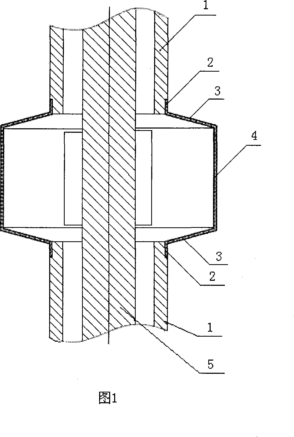
[0013] Example 1. See Figure 1. Taking a mud compensation device in an ultrasonic imaging logging tool suitable for logging in a borehole wall with a diameter of 165.1mm as an example, it will be described. The connecting section 2, the conical transition section 3 and the sound-permeable window 4 are integrally made of polytetrafluoroethylene with a wall thickness of 6 mm. The connecting section 2 at both ends is cylindrical, with an outer diameter of 90mm, and the ends of the connecting section 2 have internal threads. The sound-transmitting window 4 is in the middle of the two connecting sections 2, the sound-transmitting window 4 is a protruding cylinder with an outer diameter of 165.1mm, and the height of the sound-transmitting window 4 is 80mm. There is a cone transition section 3 between the connection section 2 and the sound-transmitting window 4. The inclination angle of the hypotenuse of the cone transition section 3 is 15 degrees. The upper connection section 2 an...


PUM


Abstract

The mud compensation device in the ultrasonic imaging logging instrument is applied to the ultrasonic imaging logging instrument, and is a mud compensation device with mud compensation function. The feature is: it consists of a connecting section, a cone transition section and a sound-transmitting window, the connecting section, the cone transition section and the sound-transmitting window are integrated as a whole, made of polytetrafluoroethylene, and the wall thickness is between 3-8mm. The connecting sections at both ends are cylindrical, with an outer diameter between 80-110mm, and the ends of the connecting sections are provided with internal threads. The sound-transmitting window is in the middle of the two connecting sections. The sound-transmitting window is a protruding cylinder with an outer diameter of 150-300mm and a height of 70-90mm. There is a cone transition section between the connection section and the sound-transmission window, and the inclination angle of the hypotenuse of the cone transition section is between 10-20 degrees. The effect is: the distance from the mud compensation device to the well wall is shortened, the propagation path of the sound wave in the mud is reduced, and the propagation attenuation of the sound wave in the mud is reduced; and the risk of sticking of the instrument in drilling can be reduced.

Description

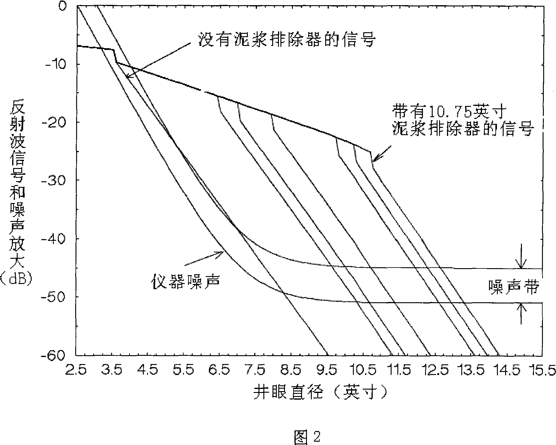
technical field [0001] The invention relates to well logging technology in the fields of petroleum and hydrogeological exploration, in particular to an ultrasonic imaging well logging instrument, in particular to a mud compensation device with mud compensation function used on the ultrasonic imaging well logging instrument. Background technique [0002] An ultrasonic imaging tool is a device that uses an ultrasonic transducer to transmit sound pulses and receive reflected wave amplitudes and travel times to generate images of the borehole wall. The ultrasonic attenuation of drilling fluid in the borehole plays an important role in the characteristics of ultrasonic imaging logging tools. High values ​​of ultrasonic attenuation in the borehole can corrupt the ultrasonic imaging logging tool image. On the one hand, high values ​​of ultrasonic attenuation in slim boreholes can cause disturbing patterns (banding) in the image. Interference modes are caused by attenuated echoes,...

Claims


Application Information

Patent Timeline
Patent Type & Authority Applications(China)
IPC IPC(8): E21B49/00G01V9/00
Inventor 朱文奎贾向东刘建成李文博贾长雨邓林贺海龙高红军葛海娅任丽娟李亚敏李剑
Owner BC P INC CHINA NAT PETROLEUM CORP
Why Eureka
Eureka Blog
Learn More