Rotary guiding drilling tool

A rotary steerable drilling and tool technology, applied in directional drilling and other directions, can solve the problems of slow directional drilling, supporting pressure, sticking of drilling tools, etc.

Inactive Publication Date: 2014-01-22
CHINA PETROCHEMICAL CORP +1
View PDF7 Cites 10 Cited by
  • Summary
  • Abstract
  • Description
  • Claims
  • Application Information

AI Technical Summary

Problems solved by technology

From the perspective of field application, sliding directional drilling technology is mature and reliable, but there are still some problems. In summary, there are mainly the following four shortcomings: First, the directional drilling speed is slow
The drilling tool does not rotate during orientation, and the power to drive the drill bit to rotate comes from the thrust generated by the worm or turbine of the power drilling tool when the mud flows. The worm or turbine rotates to drive the drill bit to rotate. This force is finally provided by the mud pump instead of the turntable. Provided, so that the rock-breaking torque obtained by the drill bit is small, and the directional drilling speed is low
Second, when the downhole friction is large, it is difficult for the drilling tool to slide forward, that is, the phenomenon of "support pressure" occurs, the drilling pressure cannot be fully added to the drill bit, and directional drilling is difficult
The third is that the tool face is not easy to stabilize, which affects the accuracy and efficiency of directional construction
Fourth, there are certain risks during orientation, and downhole accidents such as sticking of drilling tools are prone to occur

Method used


Image

  • Rotary guiding drilling tool

Examples


Embodiment Construction

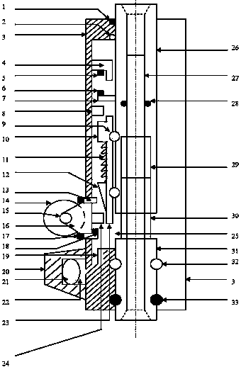
[0010] Depend on figure 1 It can be seen that the present invention is composed of non-rotating overcoat 3, rotating mandrel, guide, and orientation control mechanism. Non-rotating overcoat 3 is a hollow tubular body, and the upper and lower ends are diameter-reducing sections. A guide and a fixed centralizer 20 are installed on the wall from top to bottom; the rotating mandrel is composed of an upper rotating mandrel 26 and a lower rotating mandrel 31, and there is a Sealing ring 1 and ball 2, the lower part of the upper rotating mandrel 26 has an inner card slot 29, and the outer part is set with a ring-shaped pusher 23 through the ball 9, the lower part of the ring-shaped pusher 23 is a tapered pusher 12, and the upper part is a stopper 10. The conical push block 12 is suspended on the lower part of the stopper 10 through the spring 11; the middle part of the lower rotating mandrel 31 is the inserting rod 30 corresponding to the slot 29 in the lower part of the upper rotat...


PUM


Abstract

The invention relates to a downhole guiding drilling tool, and belongs to the technical field of petroleum engineering stratigraphical drilling downhole tools. The downhole guiding drilling tool consists of an irrotational coat, a rotary mandrel and a directed control mechanism, wherein a fixed centralizer and a guiding roller are arranged on the outer surface of the irrotational coat; the directed control mechanism is arranged in an inner cavity; and the guiding roller can be controlled to extend and retract by rotation and vertical movement of the drilling tool. When the guiding roller extends, a lateral thrust is applied to a drill bit, and a well track can forwards move along a certain direction. When extending, the roller is supported on a well wall, and the irrotational coat is prevented from rotating, but can downwards move when the drilling tool is fed, so that the purpose of directed drilling of the drilling tool under the state of rotation is realized. When retracting, the guiding roller does not have a guiding function, and the drilling tool drills like the conventional drilling tool.

Description

Technical field: [0001] The invention relates to a downhole directional drilling tool, which belongs to the technical field of downhole tools for formation drilling in petroleum engineering. Background technique [0002] In the drilling of oil and gas wells, due to the limitation of the objective conditions on the ground or the influence of many factors such as the distribution of oil layers, it is necessary to control the trajectory of the drilling wellbore so that it can advance in a certain direction, successfully drill into the oil and gas layers, and achieve the purpose of oil and gas production , Such as conventional directional wells, horizontal wells, lateral wells, multi-bottom wells, three-dimensional circumvention wells, etc. all need to use directional drilling technology. [0003] The development of sliding directional drilling technology has become mature in the late 1980s. At present, this technology is widely used in directional drilling construction. Slidin...

Claims


Application Information

Patent Timeline
Patent Type & Authority Applications(China)
IPC IPC(8): E21B7/04
Inventor 黄小仪
Owner CHINA PETROCHEMICAL CORP
Why Eureka
Try Eureka