Caterpillar belt self-walking type tunnel drilling rig hydraulic system

A hydraulic system and tunnel drilling rig technology, applied in the field of drilling machinery, can solve the problems of control lag, low hydraulic system efficiency, and low control accuracy, and achieve the effects of fast response, convenient control, and high control accuracy

Inactive Publication Date: 2008-02-13
煤炭科学研究总院西安研究院
View PDF0 Cites 19 Cited by
  • Summary
  • Abstract
  • Description
  • Claims
  • Application Information

AI Technical Summary

Problems solved by technology

[0002] At present, the relocation of full-hydraulic tunnel drilling rigs mainly relies on manual handling or short-distance movement of walking mechanisms. Only the hole power rotary d

Method used


Image

  • Caterpillar belt self-walking type tunnel drilling rig hydraulic system

Examples


Embodiment Construction

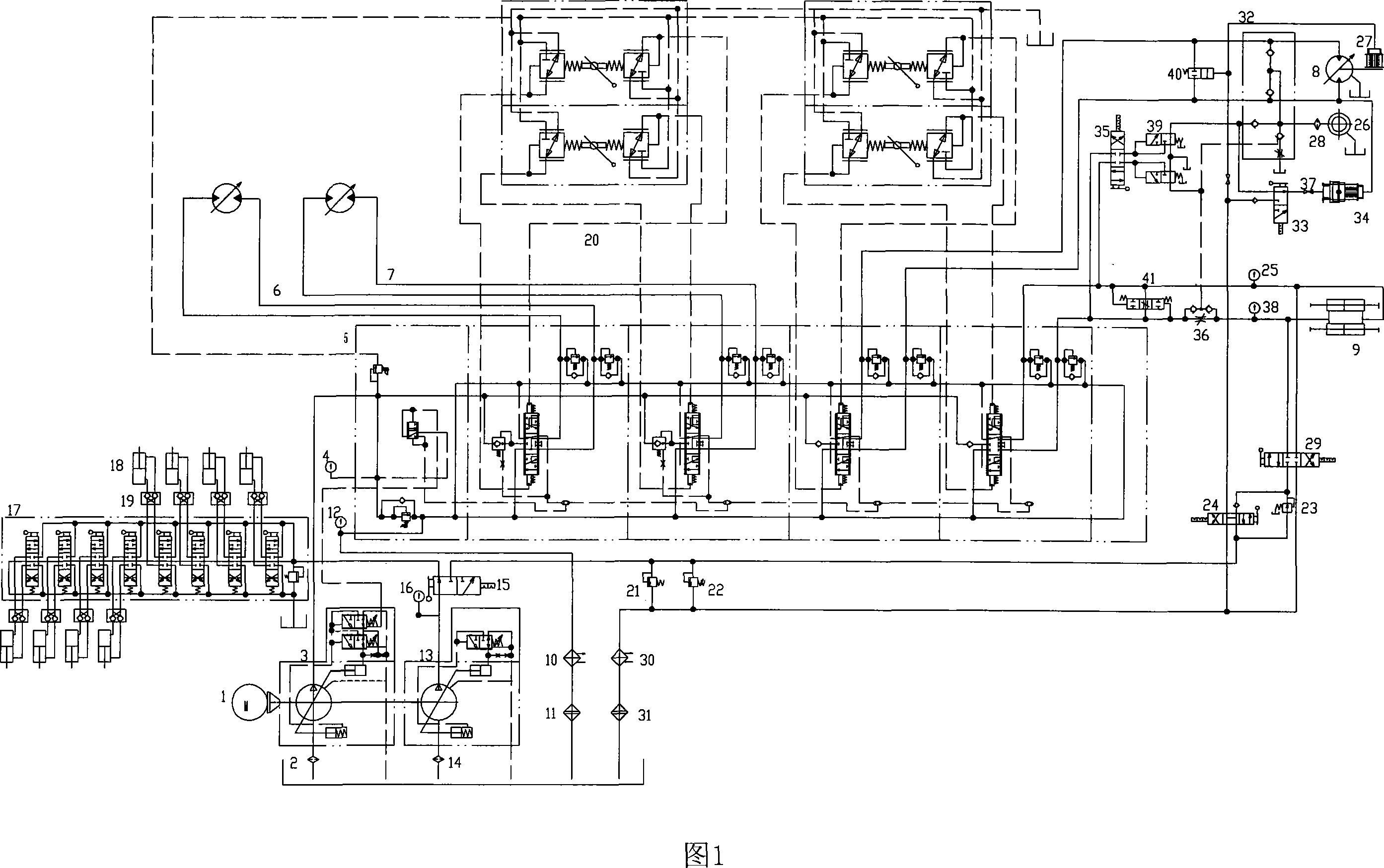
[0023] The present invention selects a load sensitive pump with advanced performance and a constant pressure variable pump to form the power device of the system, and applies the hydraulic control reversing valve and remote control technology, and uses the connection relationship between various valves to form a linkage action, so as to Adapt to different drilling operations.

[0024] The present invention adopts a load sensitive pump 3 and a multi-way reversing valve 5 with a load feedback function. Among them, the first two joints equipped with differential pressure reducing valves are used to control the travel motors 6 and 7, so as to realize functions such as straight-line travel, turning, and U-turn of the drilling rig. The third link is used to control the power head power head motor 26, and the fourth link controls the rapid movement of the feeding oil cylinder. Wherein the load sensing valve is controlled by a remote control valve 20 .

[0025] This system also adop...


PUM


Abstract

The invention is a hydraulic system of a pedrail self-walking tunnel driller. With the prior art, a fully-hydraulic tunnel driller is moved manually or by a walking mechanism for a short distance, and a rotation speed and a torque can only be controlled in the manner of drilling by power turning at a hole mouth and in the manner of manual variation. Thus, the prior tunnel driller is provided with the problem of the lagged control, the low control precision, the low efficiency of the hydraulic system, and so on. The hydraulic system of a pedrail self-walking tunnel driller of the invention comprises a pedrail walking loop, a power head turning loop, a feeding and pulling loop, a driller stabilizing loop, a brake loop of a principal axis of the power head, and so on, and can realize the straight walking and turning of the driller, the turning and feeding of the power bead, the interacting of a chuck and a clamping device with the feeding and pulling, the braking of a principal axis of a turning device, the floating of a feeding cylinder, and other functions. Moreover, as the hydraulic feedback control system and the interacting function are adopted, the driller moving is rapid and convenient, the labor intensity is low, the driller drilling techinics is widely applicable, the operation is simple and the system is energy-saving.

Description

technical field [0001] The invention relates to drilling machinery, in particular to a crawler self-propelled tunnel drilling machine hydraulic system. Background technique [0002] At present, the relocation of full-hydraulic tunnel drilling rigs mainly relies on manual handling or short-distance movement of walking mechanisms. Only the hole power rotary drilling method can be used, and the speed and torque are controlled by manual variables, which has control lag and low control accuracy. , Low efficiency of the hydraulic system and other issues. Contents of the invention [0003] The object of the present invention is to provide a crawler self-propelled tunnel drilling rig hydraulic system with convenient operation, high control precision and quick response. [0004] In order to achieve the above object, the technical scheme adopted in the present invention is: [0005] The hydraulic system of crawler self-propelled tunnel drilling rig includes drilling rig support an...

Claims


Application Information

Patent Timeline
IPC IPC(8): E21C29/22E21B7/02
Inventor 殷新胜姚宁平姚克田宏亮凡东
Owner 煤炭科学研究总院西安研究院
Why Eureka
Try Eureka