Planar display panel and planar display device

A flat-panel display and panel technology, used in identification devices, static indicators, optics, etc., can solve the problems of no structure and inconvenience in products, and achieve the effect of avoiding thermal stress problems.

Inactive Publication Date: 2008-02-13
GIGNO TECH CO LTD
View PDF0 Cites 2 Cited by
  • Summary
  • Abstract
  • Description
  • Claims
  • Application Information

AI Technical Summary

Problems solved by technology

[0008] It can be seen that the above-mentioned existing flat display panel and flat display device obviously still have inconvenience and defects in structure and use, and need to be further improved urgently.
In order to solve the problems existing in flat panel display panels and flat panel displ

Method used


Image

  • Planar display panel and planar display device
  • Planar display panel and planar display device
  • Planar display panel and planar display device

Examples


Embodiment Construction

[0063] In order to further explain the technical means and effects of the present invention to achieve the intended purpose of the invention, the following describes the specific implementation, structure, and features of the flat display panel and flat display device proposed in accordance with the present invention with reference to the accompanying drawings and preferred embodiments. And its effects are described in detail later.

[0064] Hereinafter, the flat display panel and the flat display device according to the preferred embodiments of the present invention will be described with reference to related drawings.

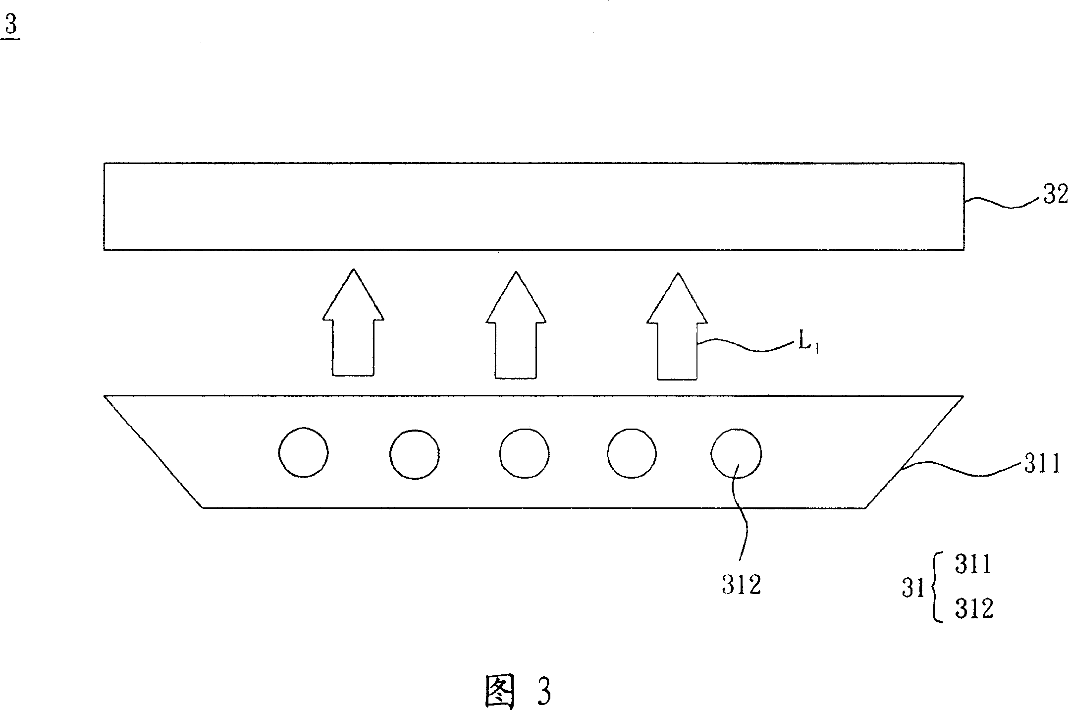
[0065] Please refer to FIG. 3, the flat display device 3 according to the preferred embodiment of the present invention has a backlight module 31 and a flat display panel 32. The flat display device 3 can be a liquid crystal display device or an organic electroluminescent display device. In this embodiment, the liquid crystal display device is taken as an example...


PUM


Abstract

The invention relates to a plane display panel and a plane display device. The plane display device is provided with a backlight module and a plane display panel; wherein, the plane display panel includes a pixel array circuit board and a first glass circuit board. The pixel array circuit board is provided with a pixel array; the first glass circuit board is provided with a first collective drive loop; wherein, the first collective drive loop is electrically connected with the pixel array. The invention makes use of the mutual electrical connection between the glass circuit board with collective drive loop and the pixel array circuit board and the collective drive loop is directly arranged on the glass circuit board, thus avoiding the thermal stress problem because of different thermal expansion coefficient.

Description

Technical field [0001] The present invention relates to a display panel and a display device, in particular to a flat display panel and a flat display device. Background technique [0002] With the demand for high image quality and the rise of the concept of environmental protection, flat display devices have gradually replaced cathode ray tube (CRT) display devices. [0003] Please refer to FIG. 1, which is a conventional flat display device, such as a liquid crystal display device, which has a liquid crystal display panel 1. The liquid crystal display panel 1 generally includes a pixel array 11, a scan line driving circuit 12 and a data line driving circuit 13. The pixel array 11 has a glass substrate G 01 And a plurality of them are arranged on the glass substrate G with amorphous silicon technology 01 Thin film transistor TFT 01 ; The scanning line drive circuit 12 is a thin film transistor TFT 01 The gate electrode is electrically connected; the data line drive circuit 13 is...

Claims


Application Information

Patent Timeline
IPC IPC(8): G02F1/133G02F1/1335G09F9/00
Inventor 萨文志
Owner GIGNO TECH CO LTD
Why Eureka
Try Eureka