

Panorama video intelligent monitoring method and system
An intelligent monitoring system and intelligent monitoring technology, applied in closed-circuit television systems, image data processing, instruments, etc., can solve the problems of consuming manpower, material resources, lack of intelligent monitoring, and inability to automatically distinguish
- Summary
- Abstract
- Description
- Claims
- Application Information
AI Technical Summary
Problems solved by technology
Method used
Image

Examples
Embodiment 1
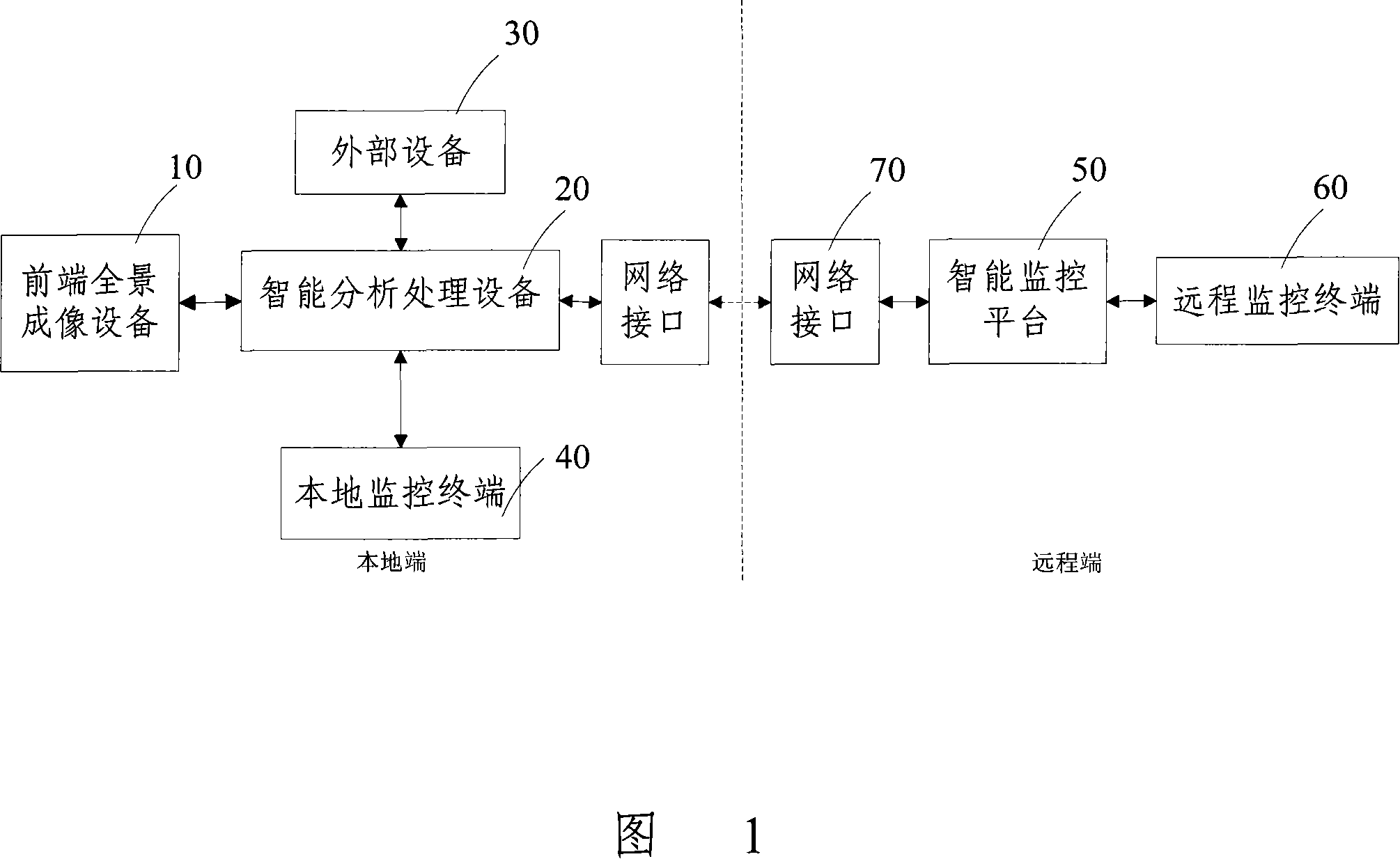
[0139] Figure 1 is a schematic structural diagram of a panoramic video intelligent monitoring system, including:
[0140] The front-end panoramic imaging device 10 is used to acquire the panoramic video information of the scene, and monitor the scene at 360° without blind spots. The front-end panoramic imaging device 10 transmits the acquired on-site panoramic video information to the intelligent analysis and processing device 20 .
[0141] The intelligent analysis and processing device 20 is used to intelligently analyze and process the on-site video information transmitted from the front-end panoramic imaging device 10. After an alarm event is detected, an alarm message is generated, and the encoded on-site video information is combined with the intelligent The analysis and processing results are sent to the intelligent monitoring platform 50 and the local monitoring terminal 40 together with the alarm information, and at the same time, the external equipment 30 is controlle...
Embodiment 2
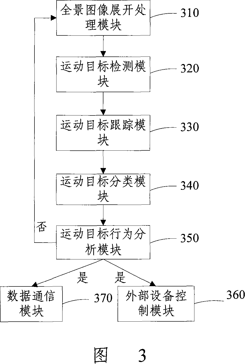
[0157] The equipment for intelligent analysis and processing of panoramic images includes modules as shown in Figure 3:
[0158] Panoramic image expansion processing module 310: used to expand the on-site panoramic image transmitted from the front-end panoramic imaging device 10, and transmit the panoramic expanded image to the moving object detection module 320;
[0159] Moving object detection module 320: used for performing object detection when the panoramic image expansion image transmitted from the panoramic image expansion processing module 310 changes, and extracting the foreground object of the current frame;
[0160] Moving object tracking module 330: for tracking the moving object detected by the moving object detection module 320;
[0161] Moving object classification module 340: for performing type identification on the moving object;
[0162] Wherein, the type identification is performed according to the detected basic data information such as the position, size...
Embodiment 3
[0182] As shown in Figure 5, it is a schematic diagram of the 360° unfolding principle of a panoramic image, and Figure 6 is a schematic flow chart of a 360° unfolding method, and the specific process of 360° unfolding is described as follows through Figures 5 and 6:
[0183] Step 601: Since the origin of the original panoramic image is at o, firstly, through coordinate transformation, the origin o of the coordinates is transferred to the center position o' of the circular panoramic image to establish a new coordinate system. Corresponding to each pixel in the image, the coordinate transformation formula is x'=x-w / 2, y'=y-h / 2, where x is the abscissa of the pixel in the panoramic image in the original coordinate system, and x' is the panoramic image The abscissa of the pixel in the new coordinate system, y is the ordinate of the pixel in the panoramic image in the original coordinate system, and y' is the ordinate of the pixel in the panoramic image in the new coordinate system...
PUM
 Abstract
Description
Claims
Application Information