
Discharge type display device

A technology for display devices and discharge electrodes, which is applied to discharge tubes, AC plasma display panels, gas-filled discharge tubes, etc., can solve the problems of rising circuit costs and insufficient solutions, and achieve the goals of reducing burdens, improving luminous efficiency, and reducing costs Effect

Inactive Publication Date: 2008-02-13
TECH TRADE & TRANSFER JP
View PDF0 Cites 0 Cited by
  • Summary
  • Abstract
  • Description
  • Claims
  • Application Information

AI Technical Summary

Problems solved by technology

However, in this case, since the occurrence of short pulses leads to an increase in circuit cost, it is not a sufficient solution.

Method used


Image

  • Discharge type display device
  • Discharge type display device
  • Discharge type display device

Examples


Embodiment Construction

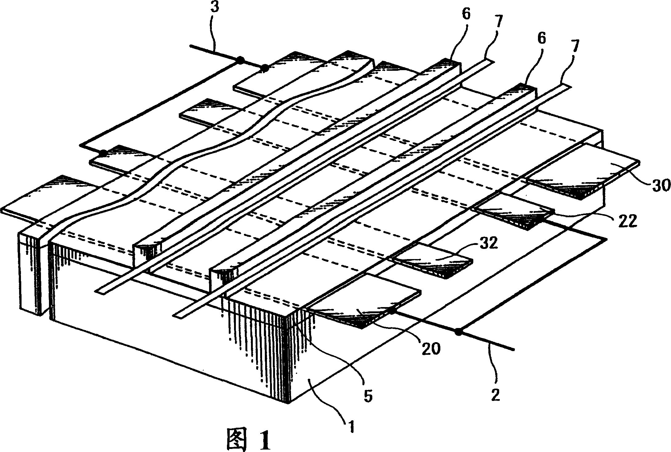
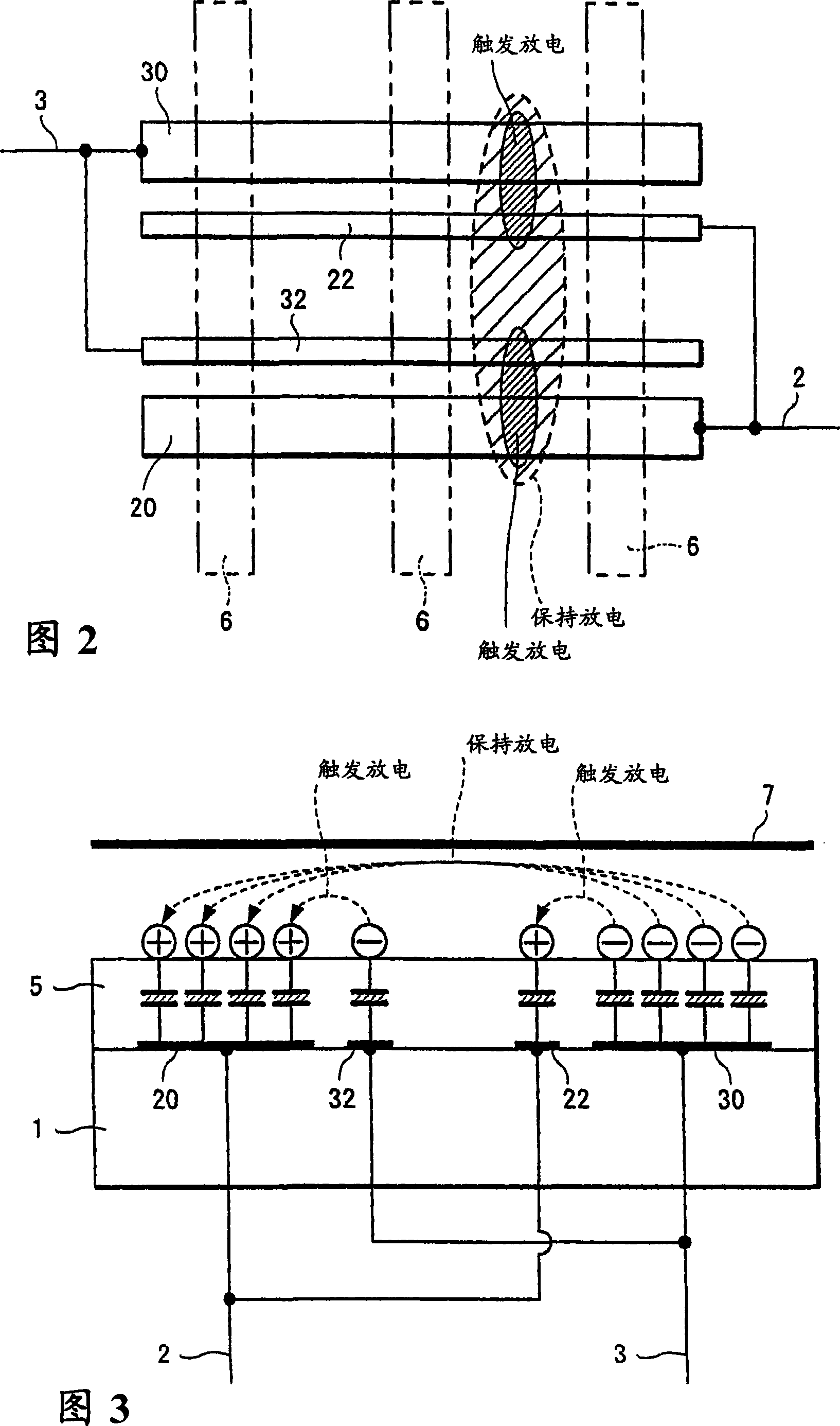
[0051] One embodiment of the first invention will be described using the developed perspective view in FIG. 1 , the electrode structure explanatory view in FIG. 2 , and the operation explanatory sectional view in FIG. 3 .

[0052] First of all, these electrodes are not limited to the combination of transparent electrodes such as ITO and Ag or Cr, Cu, Ni, etc. bus electrodes for improving conductivity used in common PDPs, and may also be opaque electrode materials. Of course, This forming substrate may be provided on the front side or on the back side.

[0053] The main discharge electrodes, that is, the sustaining electrodes 20 and 30 are covered with the dielectric layer 5 and a dielectric layer such as MgO (not shown) that has excellent secondary electron emission and good resistance to ion bombardment. Therefore, the electrodes 20 and 30 themselves may also serve as bus electrodes and discharge electrodes.

[0054] Auxiliary discharge electrodes, that is, trigger electrode...


PUM


Abstract

It has been known that the use of a positive column produced by long-gap discharge is the most promising approach of achieving a high luminous efficiency which is the most important problem of conventional PDPs. However, it has been impossible to generate an adequate positive column by means of conventional electrode structures. To ensure generation of long gap discharge, a discharge-type display device is constituted such that a trigger discharge section is provided near its main discharge electrode, and an intermediate section connecting the trigger discharge section and the main discharge section is disposed outside the screen or behind the limb, thus preventing discharge in the intermediate section and realizing only small trigger discharge and positive-column-type main discharge of high luminous efficiency.

Description

technical field [0001] The present invention relates to a discharge type display device, for example, a so-called AC type PDP (Plasma Display Panel). Background technique [0002] The PDP that is now in practical use is generally called that the surface of a pair of sheet-shaped electrodes extending in parallel is covered with a dielectric such as low-melting glass, and then the surface of the electrode with a high secondary electron emission coefficient and excellent resistance to ion bombardment is used on top of it. The so-called ACPDP is covered with an MgO layer, and the wall charge is accumulated on the surface of the above-mentioned double dielectric layer to operate, and the address electrode used for pixel selection and the sustain electrode used as the main discharge electrode for light emission are separately arranged on the front and back sides. The so-called 3-electrode surface discharge type ACPDP that shares one of the address electrodes with the above-mention...

Claims


Application Information

Patent Timeline
Patent Type & Authority Applications(China)
IPC IPC(8): H01J11/02H01J17/49
CPCH01J11/12H01J2211/245H01J11/28H01J11/24
Inventor 天野芳文
Owner TECH TRADE & TRANSFER JP
Learn More