Chromizing method by using shaft furnace

A well-type furnace and chromizing technology, which is applied in the direction of metal material coating process, coating, solid-state diffusion coating, etc., can solve the problems of short service life of box-type furnace, high production cost, difficult quality assurance, etc., and achieve direct saving The effect of production cost, saving electricity cost, and high heat transfer efficiency

Inactive Publication Date: 2008-02-20
NANJING LIMIN MACHINERY
View PDF0 Cites 0 Cited by
  • Summary
  • Abstract
  • Description
  • Claims
  • Application Information

AI Technical Summary

Problems solved by technology

[0003] The technical problem to be solved by the present invention is: the quality of the existing chromizing process using a box-type furnace is not

Method used


Image

  • Chromizing method by using shaft furnace
  • Chromizing method by using shaft furnace

Examples


Embodiment 1

[0019] Embodiment 1: During chromizing treatment, the chromizing tanks are placed in two layers in the pit furnace.

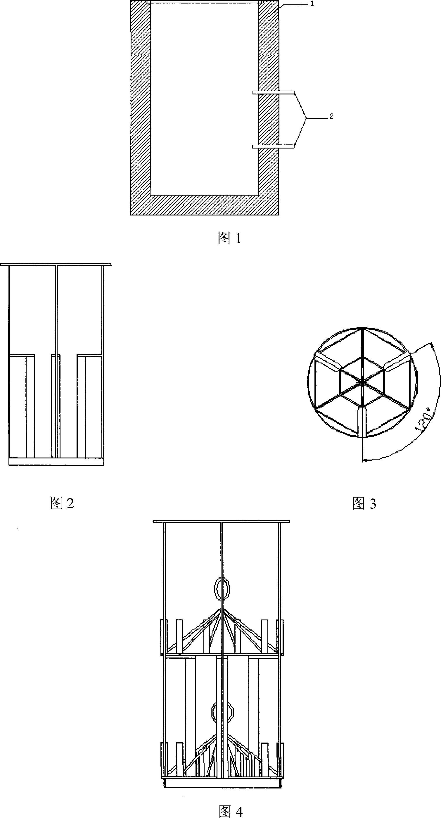
[0020] Figure 1 is a schematic diagram of the cross-section of the well-type furnace body. The outer diameter of the well-type furnace is about 2200mm, the wall thickness of the insulation layer 1 is 340-360mm, the furnace height is 1840mm, and the effective clearance of the furnace: the inner diameter is about 1450mm, and the net height is about 1500mm. Set up 2 thermocouples 2, about 600mm and 1200mm away from the bottom of the furnace, with a total heating power of 100kW, an operating temperature of ≤950°C, rapid heating up to 10-15°C / min, and good heat preservation.

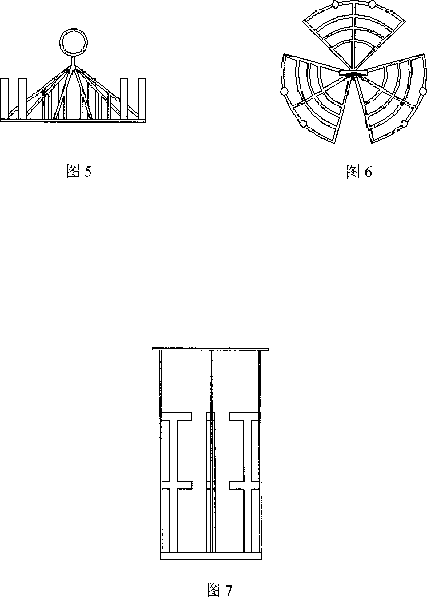
[0021] Figure 2 and Figure 3 show the protection ring and the support frame. Considering the influence of the high temperature in the furnace, the support frame and the protection ring are welded together to increase the firmness. The distance between the protective ring and the furnace wall i...

Embodiment 2

[0030] Embodiment 2: During the chromizing treatment, the chromizing tanks are placed in three layers in the pit furnace.

[0031] The pit furnace can increase the number of layers of chromizing tanks by increasing the size. Because the furnace body is enlarged, in order to ensure the furnace temperature, it is necessary to increase the number of temperature control thermocouples and increase the heating power accordingly.

[0032] The well-type furnace structure is still the same as in Example 1 when it is used in multiple layers, with an outer diameter of about 2600mm, a wall thickness of the insulation layer of 340-360mm, a furnace height of 2440mm, and an effective clearance of the furnace: an inner diameter of about 1850mm and a net height of about 2100mm. There are 3 thermocouples on the side, about 600mm, 1200mm, and 1800mm from the bottom of the furnace, the total heating power is 150kW, the operating temperature is ≤950°C, the temperature rises quickly, up to 10-15°C / m...


PUM

PropertyMeasurementUnit
Thicknessaaaaaaaaaa
Thicknessaaaaaaaaaa
Vickers hardnessaaaaaaaaaa

Abstract

The invention relates to a method applying vertical pit furnace as chromising device; at least two thermoelectric couples are arranged in the furnace to control the temperature in section with a temperature difference less than 5 centigrade. As the parts are placed evenly along the wall of the furnace, the temperature in the furnace is relative even and the heat transmission is in high efficiency, the size differences of the same parts are remarkably reduced after the chromising process; therefore, the usage precision demands of parts are ensured with a pass rate above 96 percent. The vertical pit furnace is equipped with a protective ring and a hanging bracket; the chromising jars are both carried in and out of the furnace with the bridge crane, avoiding the jar to collide the furnace wall and prolonging the life span of furnace, furnace cord and other parts. The power of the vertical pit furnace of the invention is 100kw; the chromising jars are placed in two layers in the furnace chromising 6 jars once, so that the work efficiency is increased at 1 to 2 folds. The invention can also be popularized in the parts process of other similar types.

Description

technical field [0001] The invention relates to a chromizing method, in particular to a chromizing method using a pit furnace. Background technique [0002] In current industrial production, the solid chromizing process is still widely used because of its chromizing equipment, mainly box-type furnaces, whose initial investment is small and can meet the requirements of small batch production. Chromizing of the existing box-type furnace generally uses a thermocouple to control the temperature. Since the parts are filled in the can along the axial direction, the uniformity of the furnace temperature at the front, middle and rear positions is not good, resulting in the size of the same kind of parts after chromizing The fluctuation range of the rise is relatively large. Since the chromizing atmosphere is highly corrosive, it will directly affect the heat preservation properties of the furnace body. The larger the tank volume, the problem is that the individual size differences ...

Claims


Application Information

Patent Timeline
IPC IPC(8): C23C10/32
Inventor 叶玉明徐学俊
Owner NANJING LIMIN MACHINERY
Why Eureka
Try Eureka