Light source device

A technology of light source device and retreat position, which is applied in the direction of coupling device, lighting device, light source fixation, etc., which can solve the problems of complex structure of light source device, insulation damage of reading device, inability to perform reading action, etc.

Active Publication Date: 2008-02-20
ORC MFG
View PDF2 Cites 1 Cited by
  • Summary
  • Abstract
  • Description
  • Claims
  • Application Information

AI Technical Summary

Problems solved by technology

A pulse-shaped high voltage that causes insulation breakdown between the lamp electrodes is applied from the lamp base to light the discharge lamp, so the high voltage may cause insulation breakdown of the components of the reading device.
In addition, in electrodeless discharge lamps lit by microwaves and discharge lamps lit by high-frequency current, the components of the reading device are remarkably degraded by electromagnetic waves, or normal reading operations cannot be performed.
Moreover, when the discharge lamp is lit, the surroundings of the base are in a high temperature state of about 200°C to 300°C, so the components of the reading device are degraded b

Method used


Image

  • Light source device
  • Light source device
  • Light source device

Examples


Embodiment Construction

[0017] Next, a preferred mode for implementing the present invention will be described in detail with reference to FIGS. 1 to 4 .

[0018] 【Example】

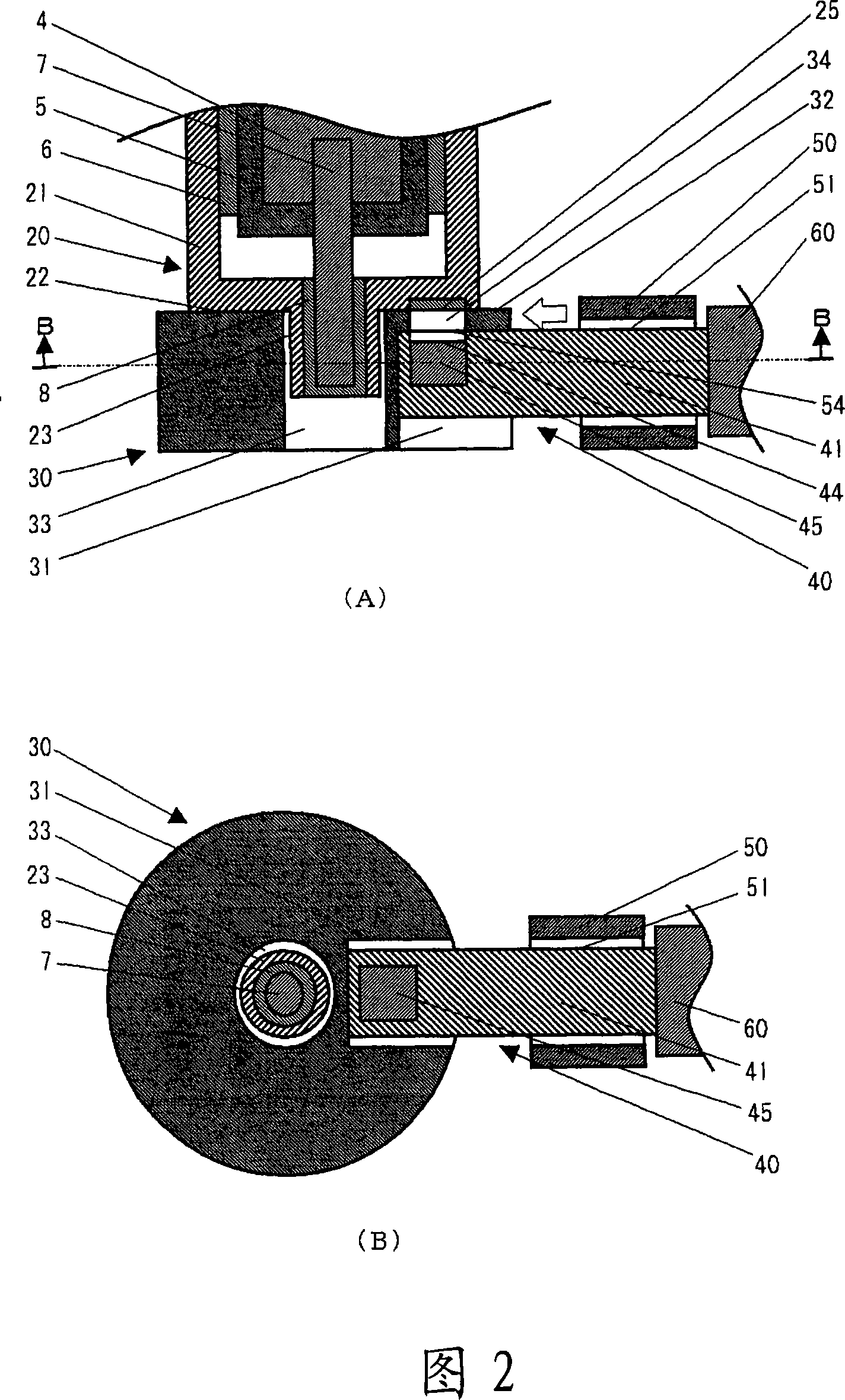
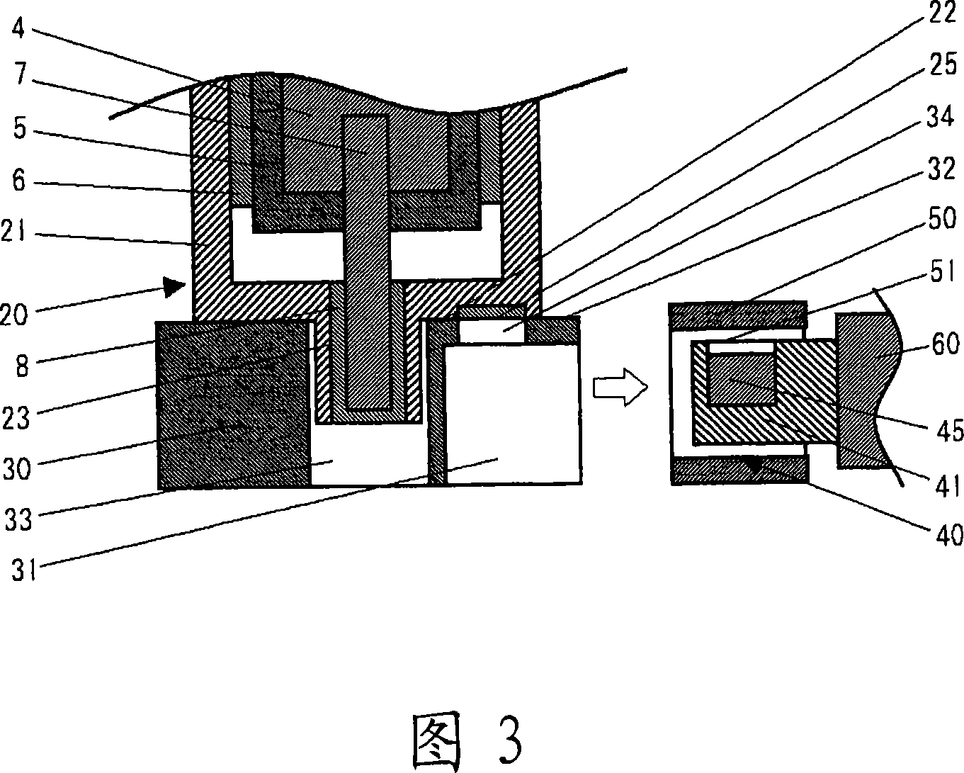
[0019] An embodiment of the present invention is a light source device in which the lamp data reading unit is inserted into the notch of the cap base when reading lamp data, and the lamp data reading unit is retracted when the discharge lamp is turned on.

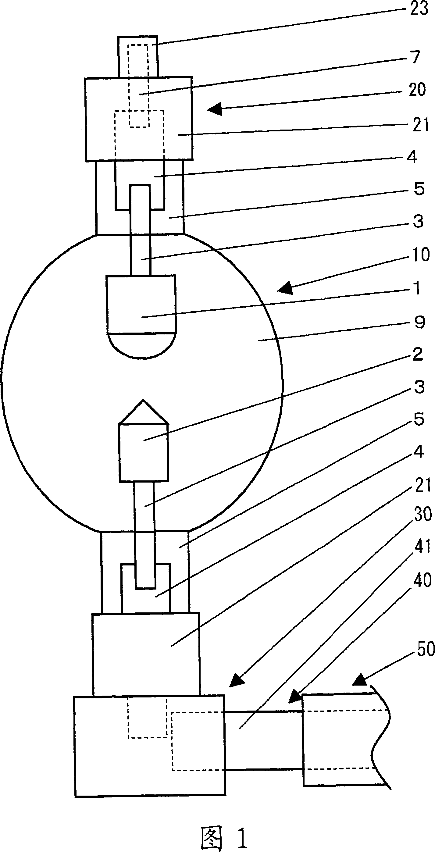
[0020] 1 is an external view showing a state in which a lamp data reading unit of a light source device according to an embodiment of the present invention is arranged to face a lamp data display unit. In FIG. 1 , the anode 1 is an electrode on the positive side. The cathode 2 is an electrode on the negative side. The inner guide rod 3 is a component that supports the electrodes and supplies power. The metal foil 4 is a member that electrically connects the inner lead rod and the outer lead rod. The sealing tube part 5 is a part which seals the bulb airtightly. The outer...


PUM


Abstract

The invention provides a lamp equipment, for preventing reading means for reading lamp data from heating or voltage injuring, on reading lamp data and managing the use state of lamp and using records. The lamp data is displayed on lamp head of lamp in advance. A reading unit of lamp data is mounted on the lamp head seat for keeping lamp head. When the lamp is kept on the lamp head seat and the lamp is not lighted, the reading unit is moved to the position of reading lamp data. Before lighting, the reading unit is moved to retreating position and a screening part for screening heat generated by lamp is mounted at the retreating position. The lamp data is lamp property such as production month and day, manufacturer name, manufacturing location, manufacturing line, lamp type, breed number, batch number, identification number and preset specification such as rated current, rated voltage, cooling condition, mounting direction on the device, operation limit time. The display format of the lamp data is optical readable bar code, two-dimensional code, character, earmark, symbol, figure, pattern and so on.

Description

technical field [0001] The present invention relates to a light source device, and more particularly, to a light source device that protects a lamp data reading unit for reading lamp data displayed on a lamp. Background technique [0002] Conventionally, the pattern of the mask for manufacturing LSI etc. is exposed to a board|substrate by the exposure apparatus which uses a discharge lamp as a light source. Before exposure, it is necessary to accurately set the positional relationship between the mask and the substrate. Therefore, in the method disclosed in Patent Document 1, the alignment mark on the mask and the substrate is imaged by an imaging device. Align the relative positions of the mask and substrate so that the two marks coincide. After the alignment is completed, the imaging device is retracted. [0003] In addition, unless the discharge lamp satisfies predetermined specifications such as wavelength and light quantity, the substrate cannot be exposed with high ...

Claims


Application Information

Patent Timeline
IPC IPC(8): F21V33/00G03F7/20
CPCF21V19/00F21V19/0005H01J5/50H01J5/52H01R33/02
Inventor 屋木康彦高津嘉郎
Owner ORC MFG
Why Eureka
Try Eureka