
Condensation tube drainage device

A technology of condensing tubes and liquid containers, which is applied to the types of heat exchangers, indirect heat exchangers, fixed conduit components, etc., and can solve the problem of increased liquid film in the lower row of condensing tubes, increased volume of heat exchange equipment, and decreased heat exchange performance, etc. problem, to achieve the effect of reducing the thickness of the liquid film, simple installation, and reducing drainage

Inactive Publication Date: 2008-02-20
张吉礼
View PDF2 Cites 11 Cited by
  • Summary
  • Abstract
  • Description
  • Claims
  • Application Information

AI Technical Summary

Problems solved by technology

However, these works did not solve the problem that the condensate in the upper row of tubes in the horizontal tube bundle of the horizontal condensing heat exchange equipment drips down, causing the liquid film in the lower row of condensing tubes to increase, resulting in a decrease in heat transfer performance (called the tube bundle effect).
At present, when designing condensing heat exchange equipment with horizontally arranged condensing tube bundles, people can only rely on increasing the number of heat exchange tubes to compensate for the adverse effect of the tube bundle effect on heat exchange, resulting in an increase in the volume of the heat exchange equipment and an increase in manufacturing costs

Method used


Image

  • Condensation tube drainage device
  • Condensation tube drainage device
  • Condensation tube drainage device

Examples


Embodiment 1

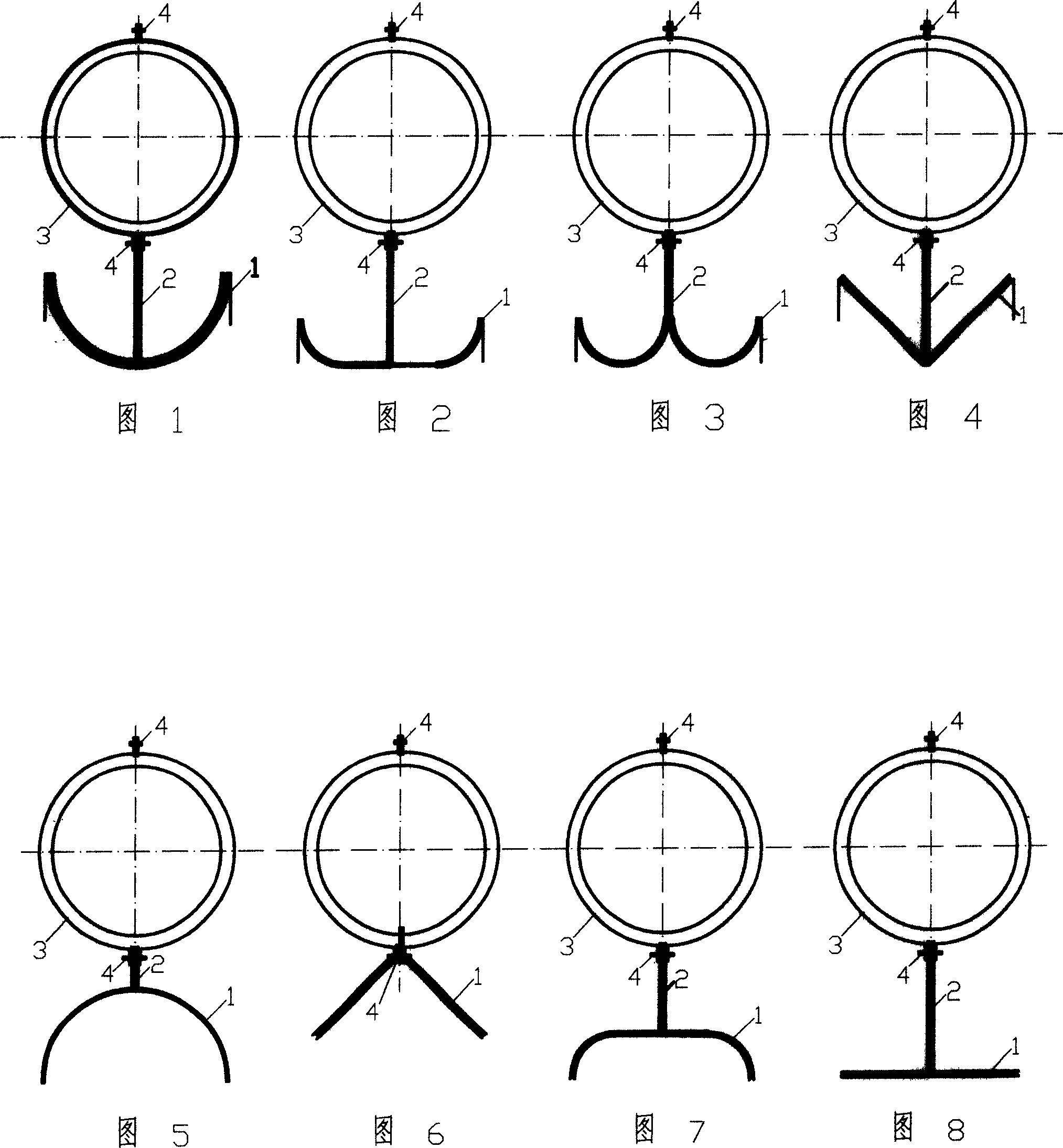
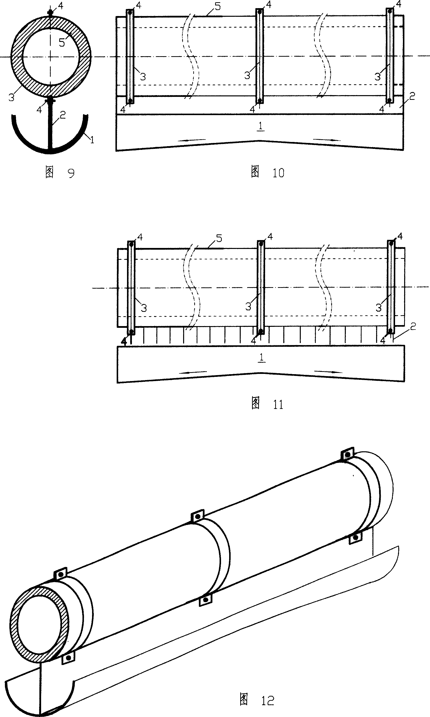
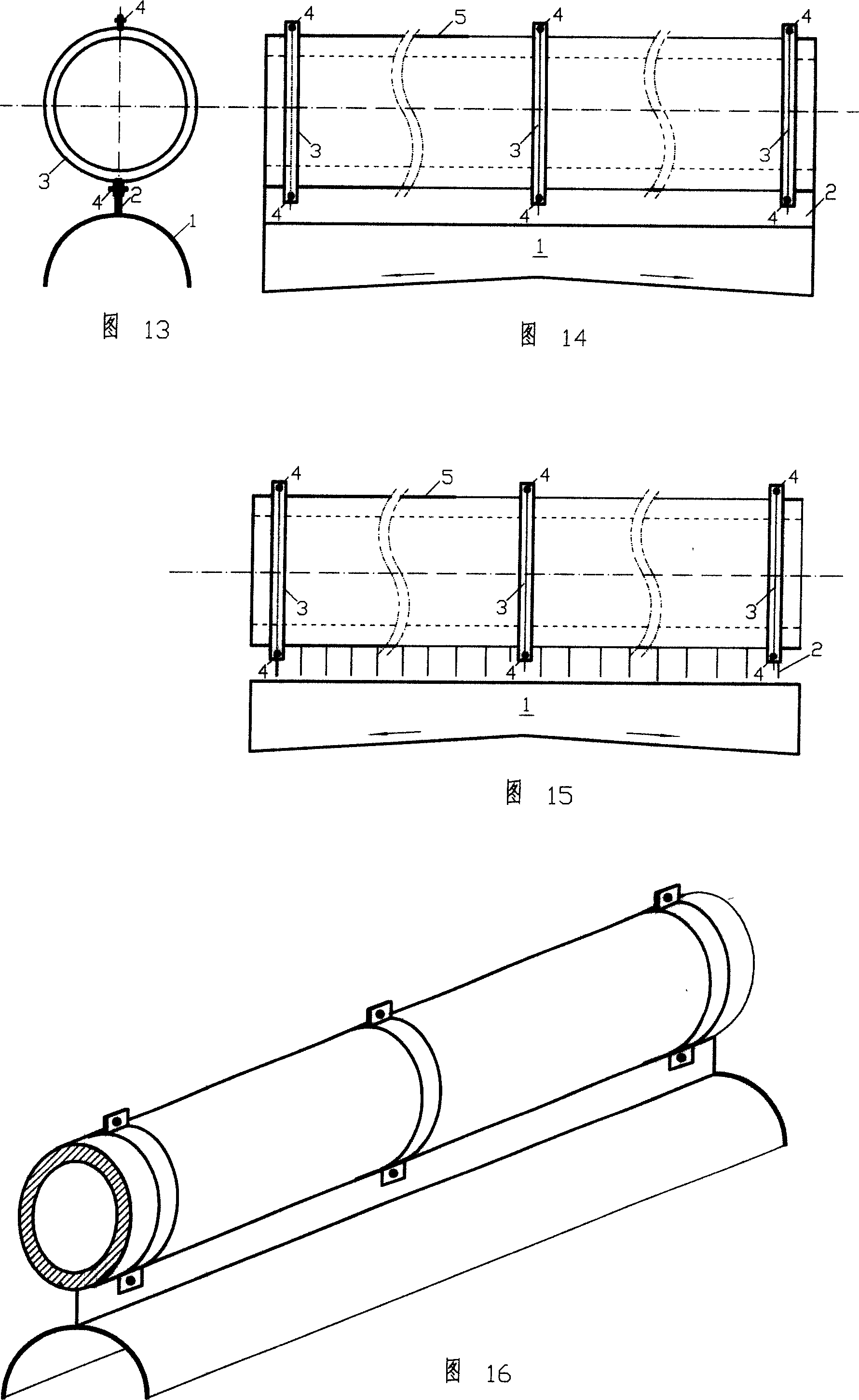
[0041] Condenser liquid guide, the composition includes: liquid guide tank 1, the upper part of the curved surface liquid guide tank 1 has a flat continuous drainage plate 2, and the liquid guide tank 1 and the described drainage plate 2 pass through the retaining spring 3 and the pin 4 Fixed on the condenser tube 5. The connection and arrangement modes in the drawings can be selected as required.

Embodiment 2

[0043] In the above-mentioned condensation pipe liquid guide, the cross-sectional shape of the liquid guide groove 1 is a curved surface, such as single arc, double arc, ellipse, etc., which can enhance heat transfer while conducting flow. In order to reduce the processing cost and adapt to different tube spacing and fluid guide volume, it can also be made into a flat plate, such as a single flat plate or a double flat plate. Liquid guide. The connection and arrangement modes in the drawings can be selected as required.

[0044] Example 2

[0045] In the above-mentioned condensation tube liquid guide, the shape of the diversion plate 2 can be a simple plane or a continuous plate in the form of a curved surface, or it can be made into a zigzag, fin-shaped, or linear grille shape according to the needs of diversion. non-continuous plate.

[0046] When the liquid guide tank used has sufficient liquid space or the distance between the heat exchange tubes is limited, the guide p...

Embodiment 3

[0048] In the above-mentioned condensation tube liquid guide, the connection between the drain plate 2 and the circlip 3 can be connected by a pin 4, or can be connected by welding, riveting, etc.; the fixing between the circlip 3 and the condensing tube 5 The method can be fixed by the pin 4, or can be directly fixed on the condensation pipe 5 by using a steel circlip with greater elasticity and strength. The connection and arrangement modes in the drawings can be selected as required.


PUM


Abstract

The utility model relates to a liquid delivery machine of the condensing pipe which is used as a liquid baffle to reduce the thickness of the condensate film outside a heat exchange pipe in a shell-and-tube heat exchanger. The condensing pipe of the prior art fails to solve the problems that the condensate drips from the upper pipe in the horizontal pipe bundle of horizontal condensation heat exchanger, which increases the thickness of the condensate film of the lower pipe and degrades the heat exchanging performance, the tube bundle effect and that the condensate converges at the bottom and increases the film thickness of the condensing pipe and the heat resistance so as to decrease the heat exchanging capacity. The utility model comprises a liquid delivery tank 1, a planar and continuous drainage plate 2 at the upper part of the liquid delivery tank 1 with a curved surface, a snap spring 3, a pin 4 and a condensing pipe 5; wherein, the delivery tank 1 and the drainage plate 2 are fixed on the condensing tube 5 by the snap spring 3 and the pin 4. The utility model can be used widely in various horizontal outside condensation heat transfer devices in the fields of petroleum, chemical industry, metallurgy, pharmacy, air-conditioning, refrigeration, heating and other fields.

Description

Technical field: [0001] The invention relates to a liquid deflector used in a shell-and-tube heat exchanger to reduce the thickness of the condensed liquid film outside the heat exchange tube. Background technique: [0002] Condensing heat exchangers are widely used in the fields of petroleum, chemical industry, metallurgy, pharmaceuticals, air conditioning, refrigeration and heating, etc. The heat exchange efficiency directly affects the industrial production cost and energy utilization efficiency, so it has always been an important research and improve objects. Since the 1970s, in order to improve the heat transfer performance of condensing heat exchangers, people have achieved a lot of fruitful results by changing the structural characteristics of the outer surface of the tube. However, these works have not solved the problem that the condensate of the upper tubes in the horizontal tube bundle of the horizontal condensing heat exchange equipment drips down, which causes ...

Claims


Application Information

Patent Timeline
IPC IPC(8): F28D3/04F28D3/02
Inventor 张吉礼马志先熊均
Owner 张吉礼
Learn More