
Double heat flux gauge steady state method for measuring material heat conductivity

A measurement method and technology of heat flow meter, applied in the direction of material thermal development, material thermal conductivity, etc., can solve the problems of heat flow density error, non-sample thermal conductivity, lack of quantitative criteria for one-dimensional heat flow conduction, etc., to overcome the inaccurate measurement. Effect

Inactive Publication Date: 2008-02-20
NANJING UNIV OF AERONAUTICS & ASTRONAUTICS
View PDF4 Cites 60 Cited by
  • Summary
  • Abstract
  • Description
  • Claims
  • Application Information

AI Technical Summary

Problems solved by technology

The above assumptions ignore the heat flow loss on the side of the sample and the contact thermal resistance between the sample and the metal block. Due to the large thermal conductivity of copper, the temperature gradient measured at adjacent positions in the copper metal block is small, so the measured pass There is a large error in the heat flux of the sample
In addition, in this method, the one-dimensional conduction of heat flow also lacks quantitative criteria, and the thermal conductivity test result is also the effective thermal conductivity of the sample including the interface thermal resistance, not the thermal conductivity of the sample itself.

Method used


Image

  • Double heat flux gauge steady state method for measuring material heat conductivity
  • Double heat flux gauge steady state method for measuring material heat conductivity
  • Double heat flux gauge steady state method for measuring material heat conductivity

Examples


Embodiment 1

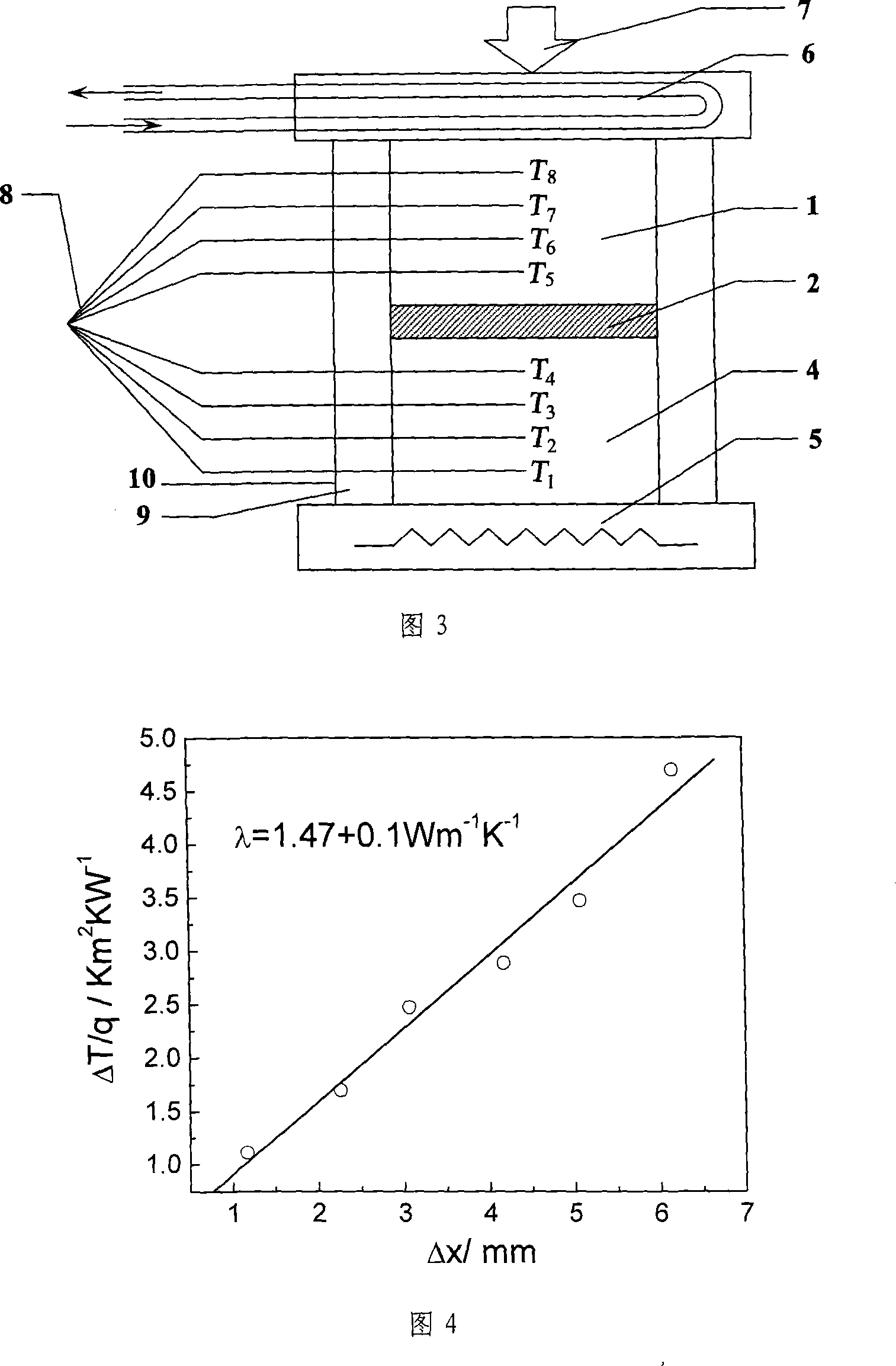
[0085] Using a group of quartz glass samples with known thermal conductivity, the thermal conductivity testing device of the present invention is used to test the thermal conductivity of the samples. The test results are shown in Table 1. The upper and lower surfaces of the sample are kept parallel and carefully ground and polished. At the same time, the upper and lower surfaces of the sample are coated with thermal conductive silicone grease to reduce the interface thermal resistance. The test sample is placed between the upper and lower heat flow metering plates, and the pressure (generally not greater than 0.7MPa) is applied through the pressure bolt on the top of the instrument.

[0086] Table 1 Test samples and test results

[0087]

[0088] Figure 4 shows the relationship curve between ΔT / q and Δx data of the quartz glass test sample, and the thermal conductivity of the quartz glass is 1.47Wm obtained from the slope of the curve in the figure -1 K -1 , with ...

Embodiment 2

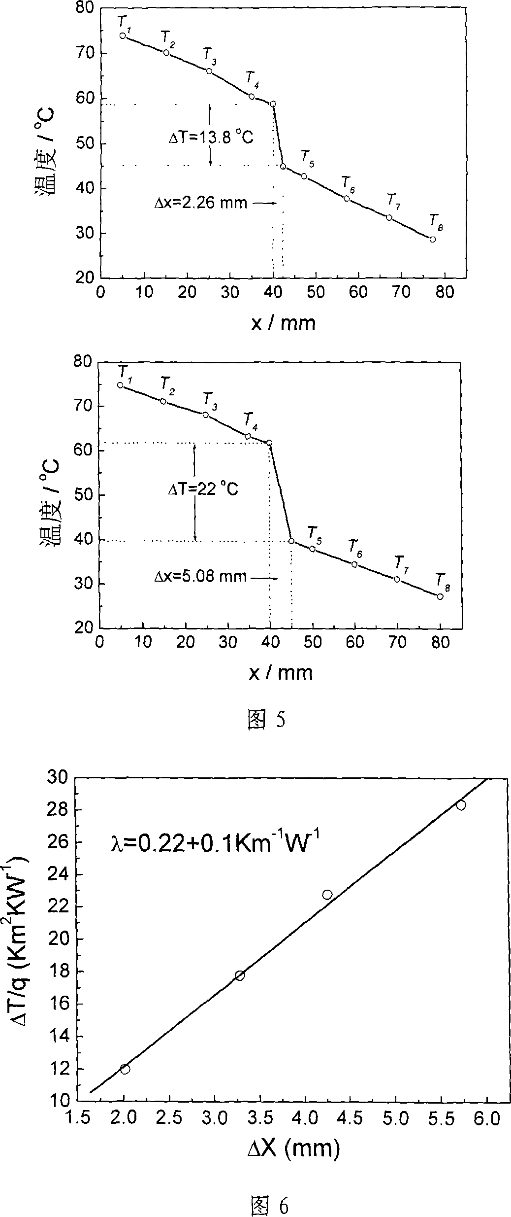
[0090] Using a group of polystyrene samples with known thermal conductivity, the thermal conductivity testing device of the present invention is used to test the thermal conductivity of the samples. The test results are shown in Table 1. Figure 6 shows the relationship curve between ΔT / q and Δx data of polystyrene test samples, and the thermal conductivity of polystyrene obtained from the slope of the curve in the figure is 0.22Wm -1 K -1 , and test data reported in literature 0.15~0.20Wm -1 K -1 In comparison, the experimental test values ​​are also in good agreement with the reported values ​​in the literature. Figure 7 shows the temperature gradient curves of heat flow through the heat flow meter and test samples with different thicknesses when the test device reaches a steady state.

Embodiment 3

[0092] Using a group of common carbon steel samples with 0.45% carbon content known to the thermal conductivity, the thermal conductivity testing device of the present invention is used to test the thermal conductivity of the samples. The test results are shown in Table 1. Figure 8 shows the relationship curve between ΔT / q and Δx data of 45 steel test samples, and the thermal conductivity of 45 steel is 41.7Wm obtained from the slope of the curve in the figure -1 K -1 , with test data reported in the literature 47.68Wm -1 K -1 In comparison, the experimental test values ​​are also in good agreement with the reported values ​​in the literature. Figure 7 shows the temperature gradient curves of heat flow through the heat flow meter and test samples with different thicknesses when the test device reaches a steady state.


PUM

PropertyMeasurementUnit
Thermal conductivityaaaaaaaaaa

Abstract

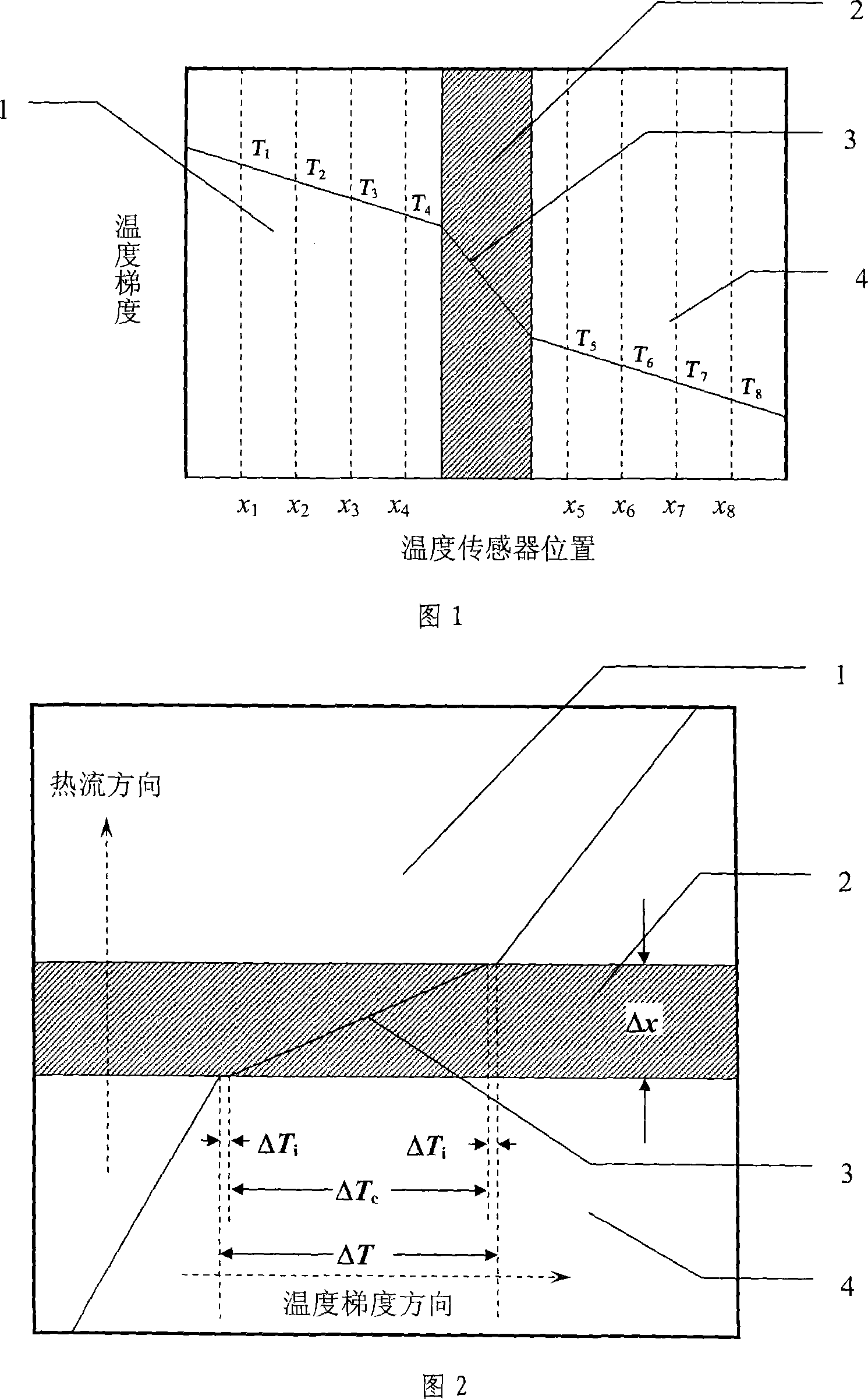
The utility model relates to a material thermal conductivity measuring method of double heat-flux meter steady-state method, belonging to the technical field of material heat conduction performance testing. Based on the analysis of one-dimensional heat conduction in multilayer flat plate, the utility model proposes the adoption of the method of double heat-flux meter and samples with different thickness for heat conduction measurement, and gives quantitative criterion of one-dimensional heat conduction. The utility model adopts multi-point temperature measurement in heat-flux meter, calculates the average heat flux density with one-dimensional heat conduction formula of multi-layer flat plate, overcomes the difficulty of inaccurate heat flux density measurement, and makes alignment-fitting calculation for the actual thermal conductivity coefficient and the interface thermal resistance with test data of samples with different thickness. In addition, the utility model can test not only the thermal conductivity of solid material, but also the thermal conductivity coefficient of film material.

Description

technical field [0001] The invention belongs to the technical field of thermal conductivity testing of materials, in particular to the thermal conductivity testing of microelectronic plastic packaging materials. Background technique [0002] The heat conduction behavior of materials has been widely concerned in the fields of thermal power, metallurgy, chemical industry, electronics, construction, aerospace and bioengineering, for example, cooling of electronic components and electronic equipment in electronic technology, heating in construction engineering Ventilation, temperature control in chemical engineering, etc. all need to know the thermal conductivity of the material, that is, the thermal conductivity of the material needs to be tested. [0003] At present, there are two methods for testing the thermal conductivity of materials: the steady-state method and the instantaneous method. Specifically, many test methods are derived according to different physical models. ...

Claims


Application Information

Patent Timeline
IPC IPC(8): G01N25/20G01N25/18
Inventor 傅仁利李克鞠生宏何洪沈源宋秀峰
Owner NANJING UNIV OF AERONAUTICS & ASTRONAUTICS
Learn More