
Welding image identification method

A recognition method and image technology, which is applied in the directions of image enhancement, image data processing, character and pattern recognition, etc., can solve the problems of limited application, not making full use of image prior knowledge, and not being able to recognize the shape and outline of the molten pool, so as to achieve applicable sexual effect

Inactive Publication Date: 2008-02-20
JIANGSU UNIV
View PDF0 Cites 21 Cited by
  • Summary
  • Abstract
  • Description
  • Claims
  • Application Information

AI Technical Summary

Problems solved by technology

[0003] After searching the existing technical documents, it was found that Xiong Zhenyu and others published "Research on Image Processing and Recognition Method of Weld Seam of Arc Welding Robot" in "Welding Technology" (2006, Vol35, No. 3: 8-11), the According to the characteristics of the weld image obtained by the charge-coupled device (CCD), the corresponding image processing method is studied, which effectively eliminates the interference of the spatter and arc light in the welding process on the weld image. The deformation at the center of the weld can be accurately identified in the image, but its shortcomings are: only the deformation of the laser band can be identified, and it cannot be applied to multi-interference image recognition without an external laser light source, and the shape and outline of the molten pool cannot be identified. For more functions such as welding quality control
However, it only recognizes local welds, and fails to recognize images containing other disturbances as a whole, which limits the application of this method
The two methods mentioned above are mainly focused on traditional image processing methods, and do not make full use of the prior knowledge of the image itself, resulting in the inability to recognize complex images and obtain good recognition results.

Method used


Image

  • Welding image identification method
  • Welding image identification method
  • Welding image identification method

Examples


Embodiment

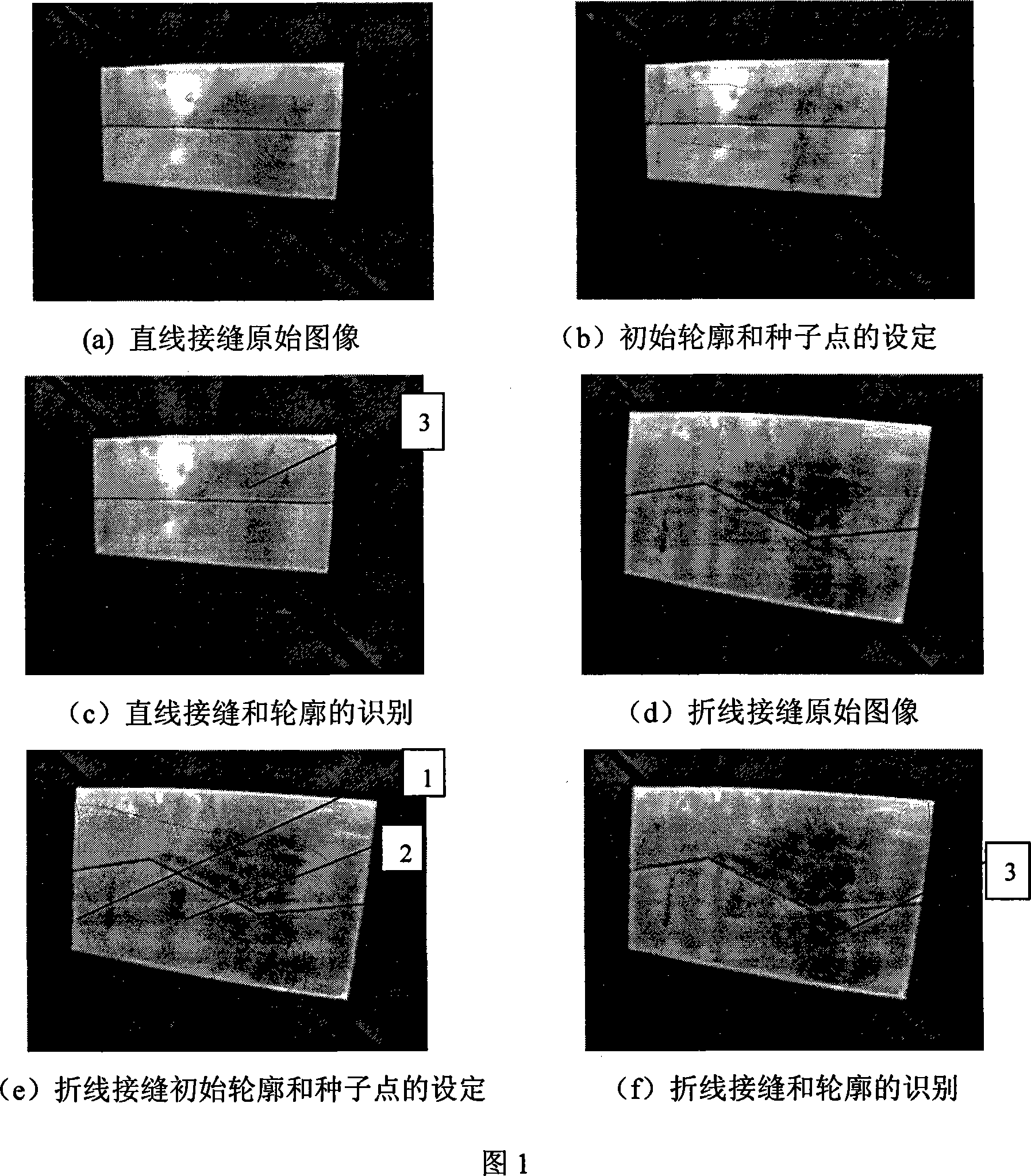
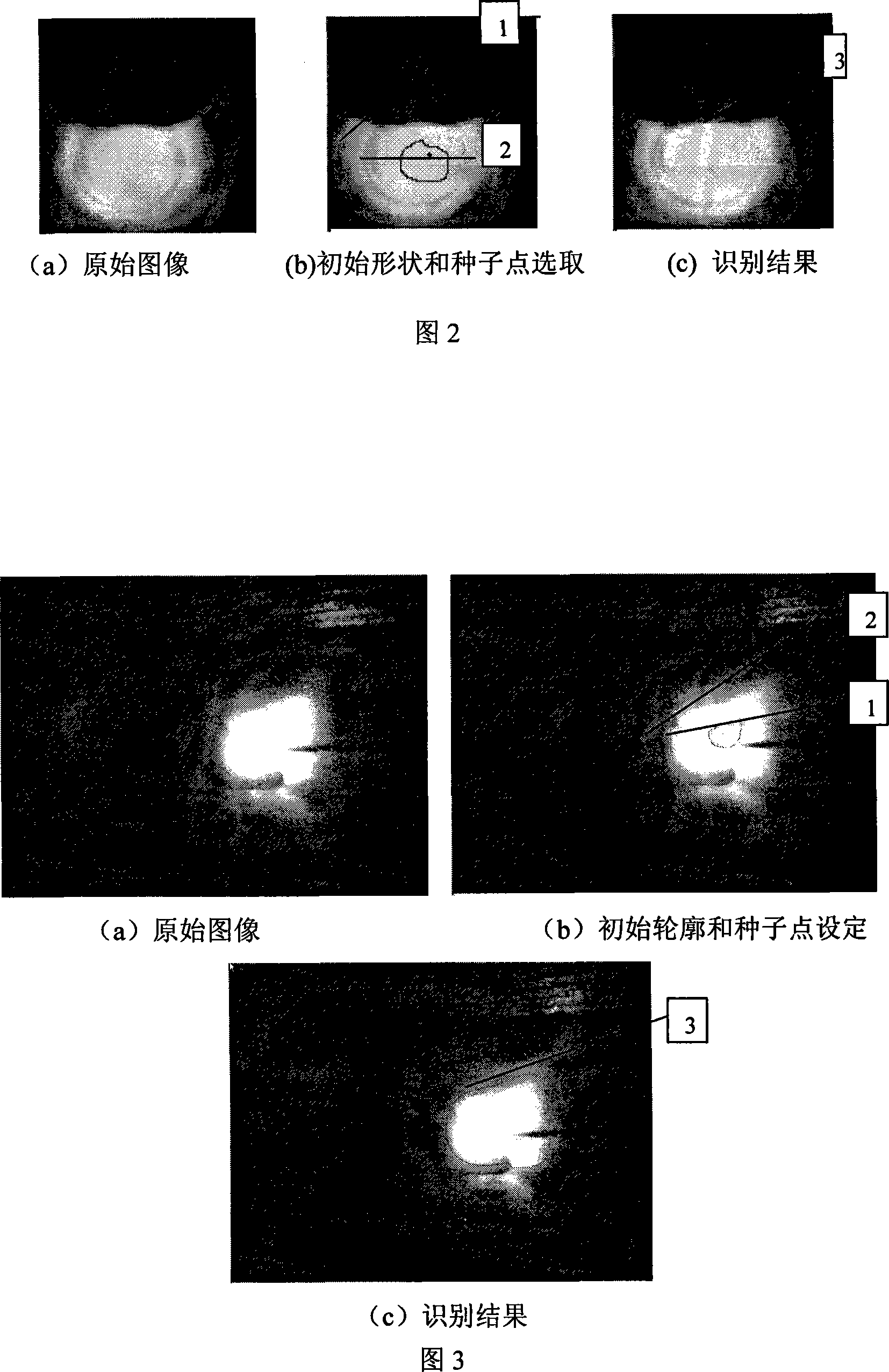
[0041] Step (1): Use the image acquisition card to convert the image of the CCD camera into a digital image. The image of the workpiece before welding is the image of the entire working environment within the field of view of the camera. It is directly collected by the CCD, and the size is 768×576. a), (d) shown. The image of the molten pool is collected according to the different needs in the production. The image of the molten pool during GTAW welding under the two conditions of filling wire and non-filling wire is collected by using a filter with a light transmission range of 590-710nm. No wire filling is used here. The size of the molten pool image during welding is 128×128, and the size of the molten pool image during wire filling welding is 400×300. The collected images are shown in Figure 2(a) and Figure 3(a) respectively. The purpose of designing this test example is to test the adaptability of the algorithm to different environments, different sizes and different sha...


PUM


Abstract

The utility model relates to a identification method of weld image based on the experiences known in the prior art, comprising: a weld seam image is acquired by a charge-coupler (CCD) and the image is processed using the C-V segmentation method; for the image to be welded, the initial contour is acquired using a CCD video camera under irradiation of general indoor light source; for the melting pool image in the welding process, the initial contour is acquired through a dimmer and filter system and used as the dividing and gradually evolved using the C-V segmentation method, thereby the actual edge shape and contour information of the pre-weld joint and the melting pool during welding process can be acquired The utility model can acquire the coordinate and the contour information of the pre-weld joint image as well as the contour information and the size information of the melting pool image, which can be use in automatic welding system or the welding robot path planning, the joint tracing and correction, penetration control and forming quality control, molding quality control, and has good applicability in the more technical fields of intelligent welding based on vision sensing technology.

Description

technical field [0001] The invention relates to the field of welding technology, in particular to a welding image recognition method based on prior knowledge, which is used to recognize seam images before welding and various molten pool images during welding. Background technique [0002] At present, visual sensing and image processing technology have been widely used in dynamic intelligent control of molten pool, weld seam tracking, prediction of welding organization, structure and robot intelligent welding. If we want to use visual technology to identify weld or extract molten pool features One of the important steps in seam tracking, penetration control, etc. is to identify welding-related images and extract the characteristic parameters of the weld or molten pool, and among these characteristic parameters, edges and contours are important characteristic quantities. For example, on a workpiece image, the gray scale of the weld seam and the workpiece forming the weld seam ...

Claims


Application Information

Patent Timeline
IPC IPC(8): G06K9/34G06T5/00
Inventor 陈希章雷玉成
Owner JIANGSU UNIV
Learn More