A cooling fan structure for permanent magnetic generator

A permanent magnet generator and cooling fan technology, applied in cooling/ventilation devices, electrical components, electromechanical devices, etc., can solve problems such as poor temperature stability, performance degradation, and reduced motor service life, so as to ensure continuous working reliability, Good air cooling effect and the effect of improving power generation efficiency

Inactive Publication Date: 2008-02-20
WUXI KIPOR POWER CO LTD
View PDF0 Cites 8 Cited by
  • Summary
  • Abstract
  • Description
  • Claims
  • Application Information

AI Technical Summary

Problems solved by technology

[0003] Among the rare earth permanent magnet materials currently used in generators, sintered NdFeB is widely used in high-power permanent magnet generators due to its large magnetic energy product and intrinsic coercive force, but sintered NdFeB permanent The remanence induction temperature coefficient of the magnet (-0.08% / ℃~-0.13% / ℃) and the intrinsic coercive force temperature coefficient (-0.5% / ℃~-0.65% / ℃) are relatively large compared with other permanent magnets, so The temperature stability is relatively poor, and the stable working temperature of sintered NdFeB is generally around 140°C
When the temperature of the motor is close to or exceeds this temperature, the permanent magnets in the motor are prone to thermal demagnetization, and a large part of this demagnetization is irreversible, which causes the power drop and performance reduction of common permanent magnet motors; another On the one hand, the temperature of the stator coil is too high, which will easily cause serious aging of the insulation and greatly reduce the service life of the motor

Method used


Image

  • A cooling fan structure for permanent magnetic generator
  • A cooling fan structure for permanent magnetic generator
  • A cooling fan structure for permanent magnetic generator

Examples


Embodiment Construction

[0018] In the following, the present invention will be further described in conjunction with the embodiments in the drawings:

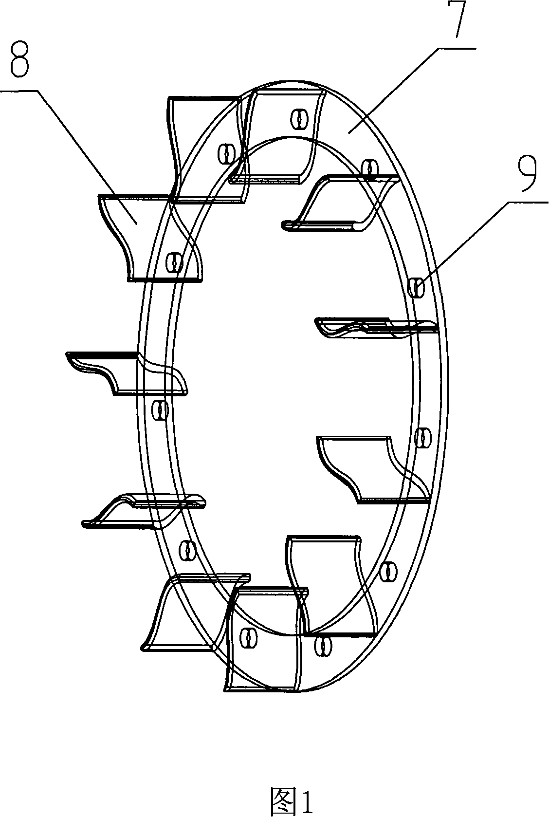
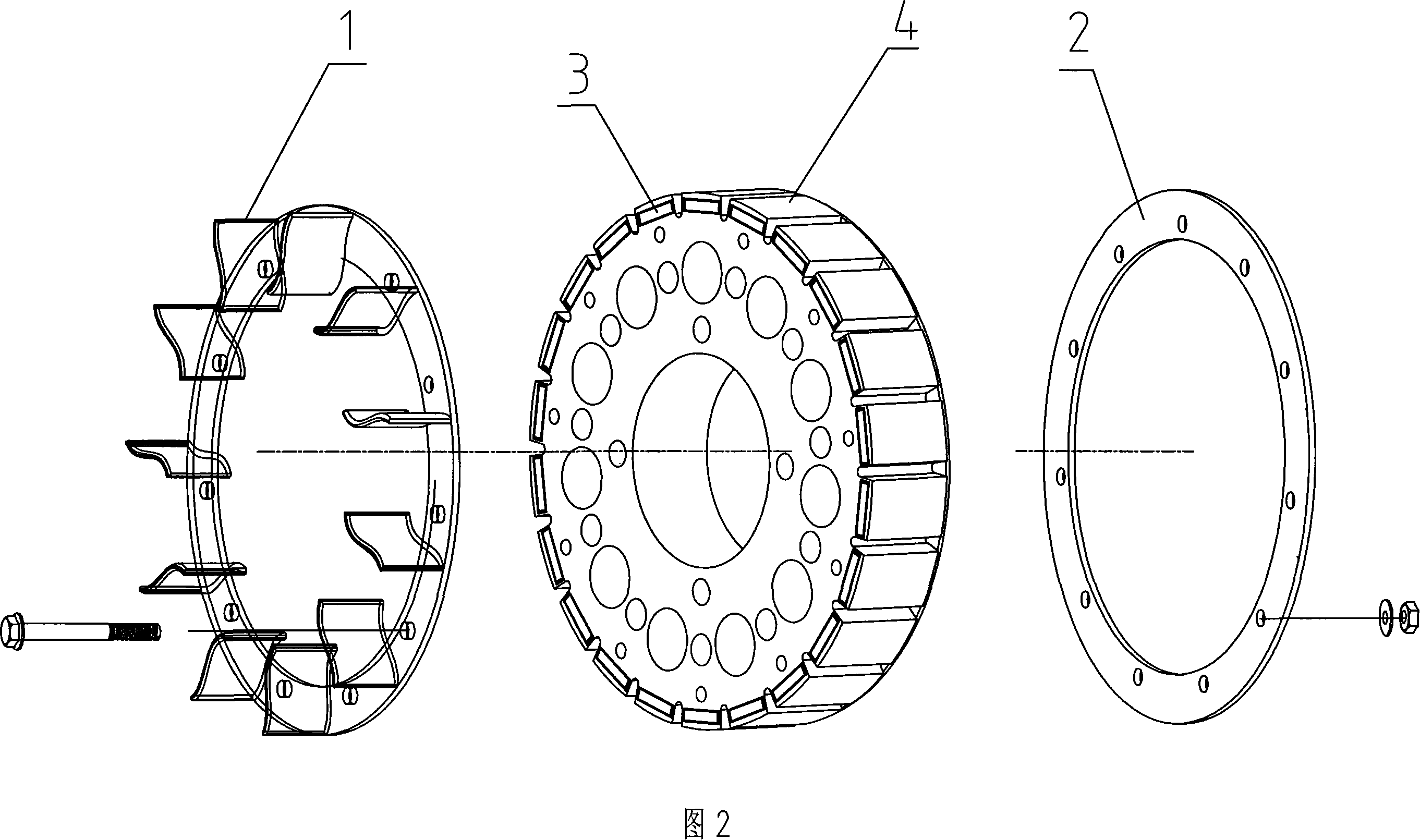
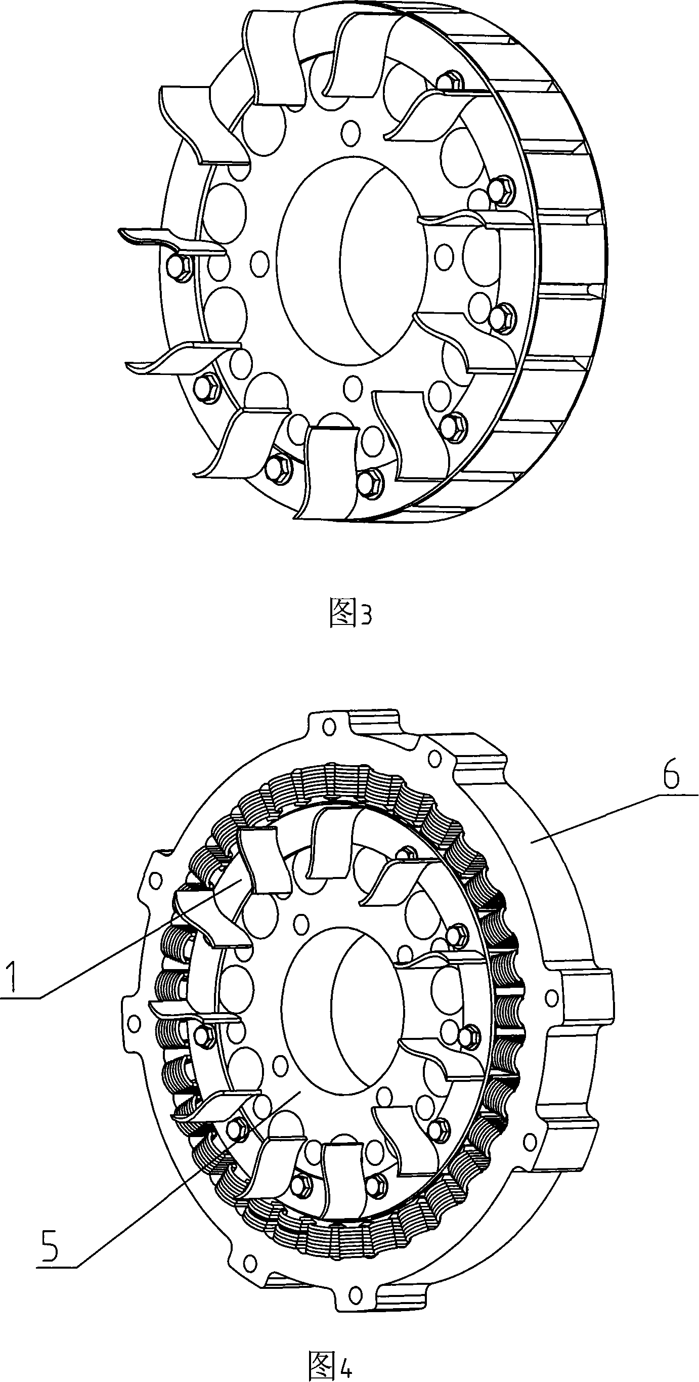
[0019] The present invention is mainly composed of a fan ring 1, a pressing ring 2, a permanent magnet 3, a rotor core 4, a generator rotor 5, a generator stator 6, a bottom plate 7, a fan blade 8 and a mounting hole 9 and so on.

[0020] As shown in Fig. 1 and Fig. 2, the present invention uses ventilation holes on the generator rotor 5. The fan ring 1 and the pressure ring 2 are installed on the generator rotor 5. The fan ring 1 and the pressure ring 2 are connected by bolts. It is connected to the rotor core 4 as a whole, and the permanent magnet 3 is installed on the protective rotor core 4. The fan ring 1 and the rotor core 4 equipped with the permanent magnet 3 are respectively arranged on both sides of the bottom plate 7, and the fan blades 8 on the fan ring The other end connected with the bottom plate 7 can be connected with a circular plate.

[...


PUM


Abstract

The utility model relates to a cooling fan structure of a permanent magnet generator, in particular to a cooling fan structure of a new-type high power permanent magnet generator, which is characterized in that a fan blade ring and a pressing ring are arranged on a rotor of the generator; the fan blade ring, the pressing ring and a rotor core are connected to a whole; a permanent magnet is arranged in the rotor core; the vane of the fan blade ring and the rotor core with the permanent magnet inside are arranged on the two surfaces of a soleplate respectively. The utility model inhales the cool air from the rotor vent to directly perform the wind cooling on the generator rotor core and the stator coil through the self-centrifugal fan blade ring arranged on the generator rotor so as to ensure the smooth airflow, reduce the heat conduction from the stator to the permanent magnet of the rotor; with the excellent wind cooling performance, the utility model has the advantages that the continuous working reliability of the permanent magnet generator can be ensured; the soleplate is made of low-magnetic permeability material so as to perform the magnetoresistive function on the permanent magnet of the rotor and increase the generating efficiency of the generator.

Description

Technical field [0001] The invention relates to a cooling fan structure of a permanent magnet generator, in particular to a cooling fan structure of a novel high-power permanent magnet generator. Background technique [0002] When the permanent magnet generator is working, due to the impedance of the stator coil, heat will be emitted when the current passes, and the temperature inside the motor body is relatively high. Especially for the current high-power diesel digital generator set, the permanent magnet generator is equipped with Due to the miniaturization of the appearance, there is generally no cooling fan, but the free circulation of air in the case cools the generator, so that the unit cannot run continuously for a long time. Because there is no direct cooling of the generator, the heat generated by the stator coil cannot be quickly discharged, causing the temperature of the rotor with permanent magnets to rise quickly. For permanent magnet generators, temperature is the f...

Claims


Application Information

Patent Timeline
Patent Type & Authority Applications(China)
IPC IPC(8): H02K9/04
CPCH02K9/06
Inventor 肖亨琳
Owner WUXI KIPOR POWER CO LTD
Why Eureka
Try Eureka