Surrounding photograph monitoring device and its method

A monitoring device and surrounding field technology, which is applied in closed-circuit television systems and other directions, can solve the problems of small screen, front, back, left and right cannot be effectively considered, and cannot be displayed, so as to improve safety, reduce installation space and cost, The effect of improving usability

Inactive Publication Date: 2008-02-20
林士进
View PDF0 Cites 0 Cited by
  • Summary
  • Abstract
  • Description
  • Claims
  • Application Information

AI Technical Summary

Problems solved by technology

[0004] However, although the existing photographic device has the effect of surround-field photographic display, it has many inconveniences for users:
[0005] 1. The existing method only has four directions of photography angles, and can only shoot four angles of upper left, upper right, lower left, and lower right, and cannot effectively take into account front, rear, left, and right, so there are quite a lot of dead angles
[0006] 2. This method of cutting and separating multiple screens to present images of environmental conditions is closer to the compound eye visual system of insects, which is inconsistent with the presentation of human visual images, so it is difficult for users to observe quickly. Interpreting the state of the surrounding environment, it is more difficult to watch four screens at the same time while driving
[0007] 3. The design of displaying surrounding images on multiple screens requires more space for the installation of display devices, which not only greatly increases the cost, but also makes it difficult to find a suitable installation place in the car, so it is difficult to break through in practical implementation However, if all the output images are displayed on a split screen, it is not easy to observe because the screen is too small
[0009] 1. A two-dimensional picture with a virtual image and a top view angle. For columnar objects such as utility poles, triangular cones, traffic lights, etc., they are only represented by a circle in the picture. It is difficult for users to identify and accurately grasp the surrounding obstacles. The height, shape, and distance of the virtual image lack authenticity and presence
[0010] 2. For the detailed changes of the surrounding objects, such as the change of the direction of the wheels of the vehicle, or the support of the motorcycle driver's feet on the ground, the existing mapping methods cannot be displayed in the virtual screen one by one, so the user cannot grasp it. Changes in details
[0011] 3. The existing virtual method must first assume that the regional scene is located on a flat road, so that the virtual image calculation process can be applied to synthesize the scenes captured by each camera into the monitoring screen in the form of virtual textures. However, if the terrain does not meet the requirements of a flat road surface when going up and downhill or on a bumpy slope, it will cause inconvenience that the virtual picture does not match the real scene or the difference is too large
[0012] 4. The existing two-dimensional virtual screen is calculated and synthesized, so it is inevitable to have a certain degree of error, and the change in height cannot be seen at all. For the protruding foreign objects on the roadside, such as safety islands, separation islands and other objects cannot be displayed , unable to provide a monitoring system that users can fully trust
[0013] It can be seen that the existing monitoring system, whether it is the former real-scene split screen or the latter's virtual composite screen, both design methods have their insurmountable shortcomings, and their practicability is poor, and there is still a need for improvement

Method used


Image

  • Surrounding photograph monitoring device and its method
  • Surrounding photograph monitoring device and its method
  • Surrounding photograph monitoring device and its method

Examples


Embodiment Construction

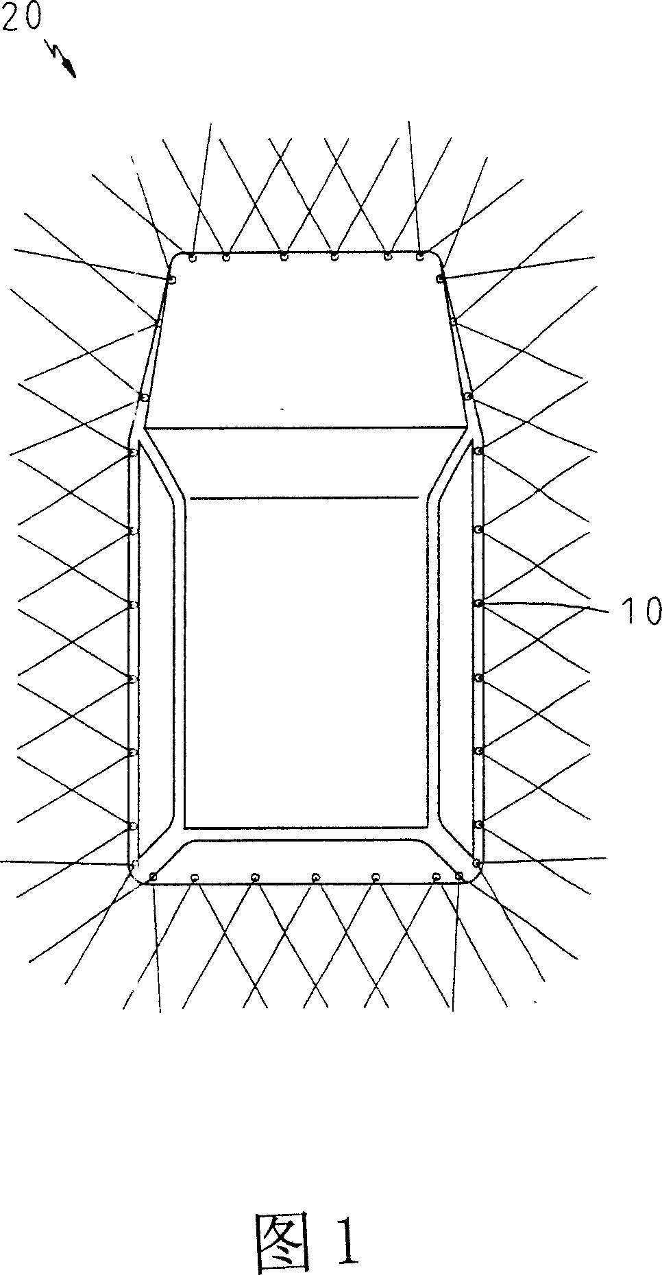
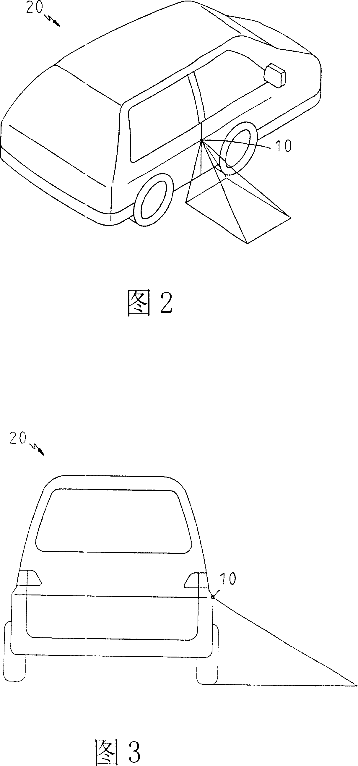
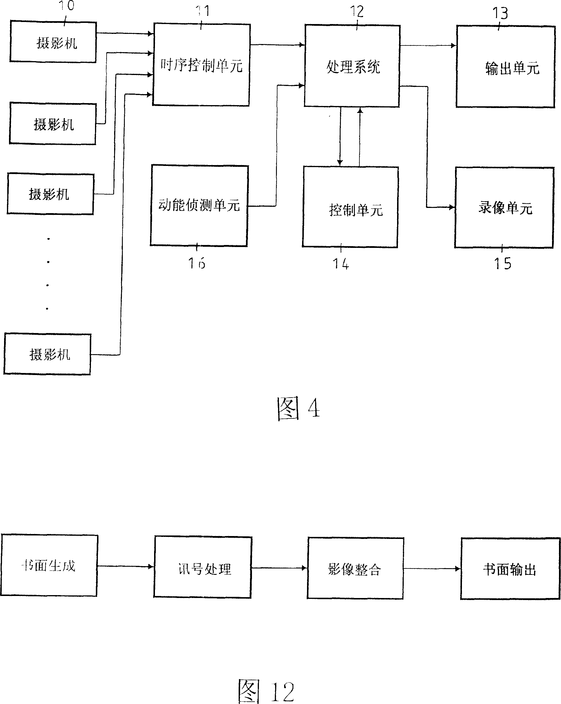
[0053]The present invention relates to an around-field photographic monitoring device and a method thereof. The around-field photographic monitoring device is shown in Figs. 1 to 4. It is mainly used in any area that needs to be observed and monitored. The camera 10 is It is connected to a timing control unit 11, which is connected to a processing system 12, and finally the surrounding scene is presented by the output unit 13. For the convenience of description, the area is a car body in this embodiment. 20 as an example;

[0054] The plurality of cameras 10 are arranged around the vehicle body 20, and the installation method of a camera 10 approximately every 30 degrees is the best. The imaging ranges between the cameras 10 are partially overlapped, and the plurality of cameras 10 are used to control the vehicle. The scene around the body 20 is photographed and imaged, and the picture signal adjusted to a predetermined resolution is sent to the timing control unit 11. The picture...


PUM


Abstract

The utility model relates to a monitoring device and method for the toroidal field photography, which comprises a plurality of cameras, a processing system and an output unit; the video signals captured by the cameras are adjusted and integrated to the same toroidal picture through the processing system, and the toroidal picture is shown by an output unit; the toroidal picture takes the center of the area in which the camera is arranged as the hub, and all the scenes taken by cameras are arranged in the corresponding positions in the toroidal picture in three-dimensional live-action mode. The method comprises the following steps: generating the pictures: capturing the surrounding scenes with a plurality of cameras; processing the signals: controlling the cameras in time sequence by the sequential control unit; integrating the images: the processing system adjusts the picture signal from cameras; outputting pictures: the output unit displays the toroidal field picture integrated by the processing system y. The utility model has the advantage of improving the overall security and reducing the space and cost of display units.

Description

Technical field [0001] The invention relates to a surrounding field photography monitoring device and a method thereof. Background technique [0002] Due to the advancement of photographic equipment and image processing technology, modern people can break through the limits of human vision through surveillance systems and provide various environmental information control functions; such as reversing surveillance systems or home security surveillance, and even mountain disaster search and rescue. , Can be done with photography and image processing devices, eliminating blind spots that were originally invisible to the naked eye, and improving the safety and convenience of life. [0003] At present, there are already cameras installed at various angles around the object to present the surrounding 360-degree environment for users to observe the equipment, such as China Taiwan Certificate No. M247463, "Automobile Photography Auxiliary Safety Device", which mainly uses four The cameras...

Claims


Application Information

Patent Timeline
Patent Type & Authority Applications(China)
IPC IPC(8): H04N7/18
Inventor 林士进
Owner 林士进
Why Eureka
Try Eureka