Differential thermomagnetic switch

A switch and thermomagnetic technology, applied in the direction of switches with electric heating and electromagnetic release, protection switches, circuit breaker contacts, etc., can solve the problems of high manufacturing and assembly costs, complex switches, etc.

Inactive Publication Date: 2010-05-19
VIMAR SPA
View PDF5 Cites 0 Cited by
  • Summary
  • Abstract
  • Description
  • Claims
  • Application Information

AI Technical Summary

Problems solved by technology

[0003] However, a major disadvantage of prior art differential thermomagnetic switches is the inclusion of a large number of parts which must be properly assembled in order to ensure quick and safe separation of the electrical contacts of the switch
In addition to making the switch overly complex, this results in higher manufacturing and assembly costs

Method used


Image

  • Differential thermomagnetic switch
  • Differential thermomagnetic switch
  • Differential thermomagnetic switch

Examples


Embodiment Construction

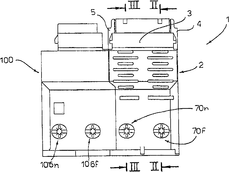
[0029] figure 1 A complete form of the differential thermomagnetic switch according to the invention is shown, which is designated as a whole by the reference numeral 1 .

[0030] The switch 1 has two box-like components next to each other: a thermomagnetic switch component 2 and a differential circuit component 100 .

[0031] The thermomagnetic switch unit 2 comprises a double-sided intermediate wall 3 which defines and separates two opposing housings 3f and 3n:

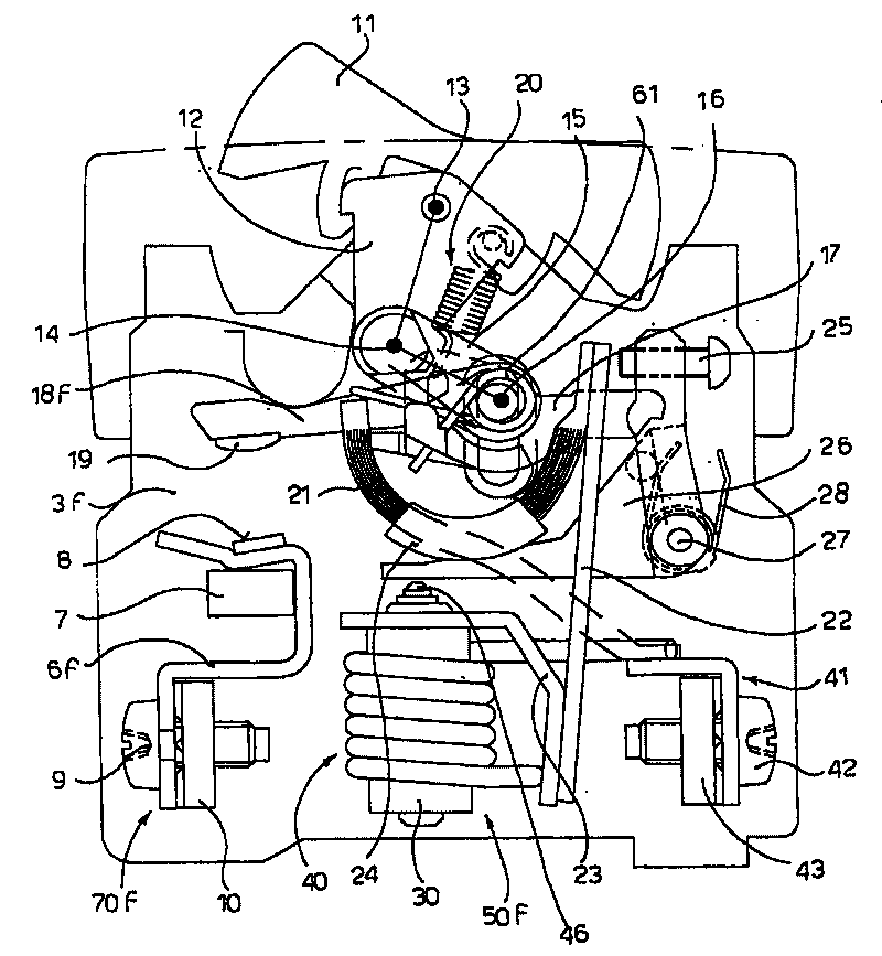
[0032] - the first housing 3f ( figure 2 ), which is called a phase housing since it houses the fixed contacts 6f connected to the phase line (supply line) of the electrical system, and

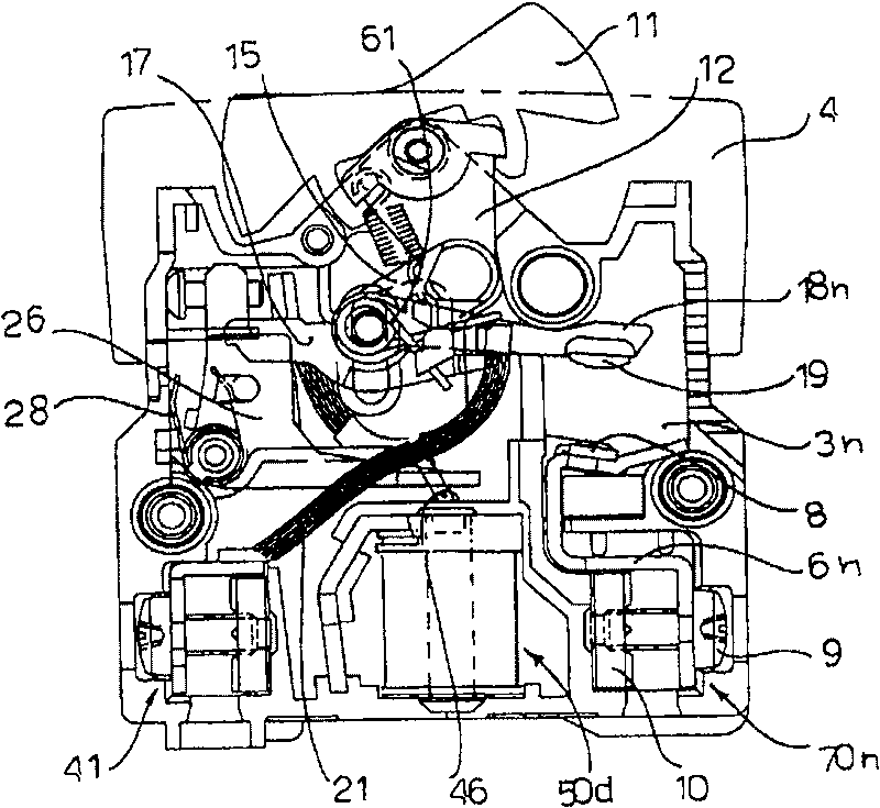
[0033] - the second housing 3n ( image 3 ), because it houses the fixed contact 6n connected to the neutral wire (ground wire) of the electronic system, it is called the neutral housing.

[0034] back to figure 1 , said housings 3f and 3n are covered by removable covers 4 and 5, respectively.

[0035] In the following, spec...


PUM


Abstract

A thermomagnetic switch (1) is described comprising: a box-type body comprising an intermediate wall (3) which defines respective phase and neutral housings (3f, 3n), movable phase and neutral contacts (18f, 18n) destined to come into contact with respective fixed phase and neutral contacts (6f, 6n), a kinematic mechanism connected to the mobile contacts (18n, 18f) to bring them from a closed position to an open position, a push button (11) that can be operated from the outside and that is connected to the kinematic mechanism, and a coupling lever (26) - connected to the kinematic mechanism -which can be operated through the intervention of a thermal (22) and / or of an electromagnetic (50f) and / or of a differential device (100, 50d). The kinematic mechanism comprises a contact-carrying lever (117) made in a single piece and provided with two arms (121), which extend into the phase and neutral housing (3f, 3n). Each arm (121) comprises a seat (118) able to receive the respective movablephase and neutral contact (18f, 18n).

Description

technical field [0001] The present invention relates to a thermal-magnetic or differential thermo-magnetic automatic switch which is small in size and is particularly suitable for module installation in civil supports and series plates, in order to protect the user from short circuits and said automatic Effect of overcurrent on switching downstream equipment. Background technique [0002] Differential thermo-magnetic switches for switching on / off power supply circuits when short circuits, overloads or leakage currents are detected in equipment downstream of automatic switches are currently in widespread use in the market. These switches have a high breaking capacity, that is, they can quickly separate electrical contacts when an anomaly is detected in downstream equipment. [0003] However, a major disadvantage of prior art differential thermomagnetic switches is that they include a large number of parts which must be properly assembled in order to ensure quick and safe sep...

Claims


Application Information

Patent Timeline
Patent Type & Authority Patents(China)
IPC IPC(8): H01H71/00H01H71/10H01H73/52
CPCH01H71/002H01H83/14H02G3/123H01H71/1009H01H73/04H01H73/52
Inventor P·C·古西
Owner VIMAR SPA
Why Eureka
Try Eureka