Power conversion apparatus

A power conversion device and electric power technology, which is applied in the direction of output power conversion device, electrical components, and adjustment of electric variables, etc., can solve the problems of power regulator efficiency reduction, difficulty in miniaturization of the device, and increase in chopper loss.

Inactive Publication Date: 2008-02-20
MITSUBISHI ELECTRIC CORP
View PDF0 Cites 8 Cited by
  • Summary
  • Abstract
  • Description
  • Claims
  • Application Information

AI Technical Summary

Problems solved by technology

If the step-up rate is high, the loss of the chopper section increases, and the efficiency of the power conditioner as a whole decreases
[0006] In addition, since the PWM switching operation us

Method used


Image

  • Power conversion apparatus
  • Power conversion apparatus
  • Power conversion apparatus

Examples


Embodiment approach 1

[0048] Hereinafter, a power conversion device (hereinafter referred to as a power conditioner) according to Embodiment 1 of the present invention will be described with reference to the drawings.

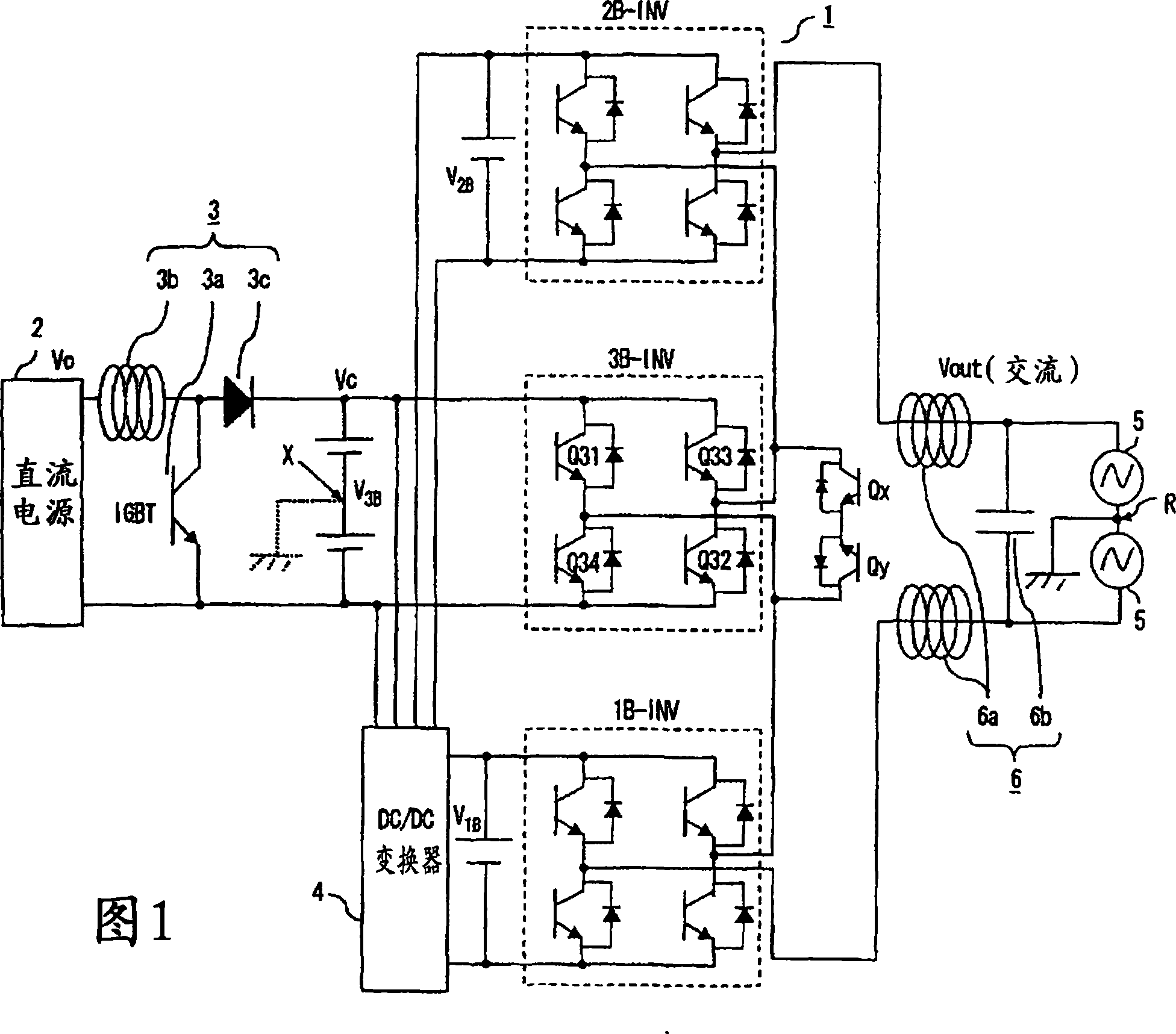
[0049] FIG. 1 is a schematic configuration diagram showing a power conditioner according to Embodiment 1 of the present invention. As shown in Fig. 1, multiple (in this case, three) single-phase inverters 2B-INV, 3B-INV, and 1B-INV are connected in series on the AC side to form an inverter as a single-phase multiple converter. device unit 1. Each of the single-phase inverters 2B-INV, 3B-INV, and 1B-INV is composed of self-arcing semiconductor switching elements such as a plurality of IGBTs connected in antiparallel with diodes. 3B The single-phase inverter 1B-INV is connected to one of two terminals on the AC side of the input single-phase inverter 3B-INV, and the other is connected to the single-phase inverter 2B-INV. In addition, as a short-circuit switch for short-circuiting be...

Embodiment approach 2

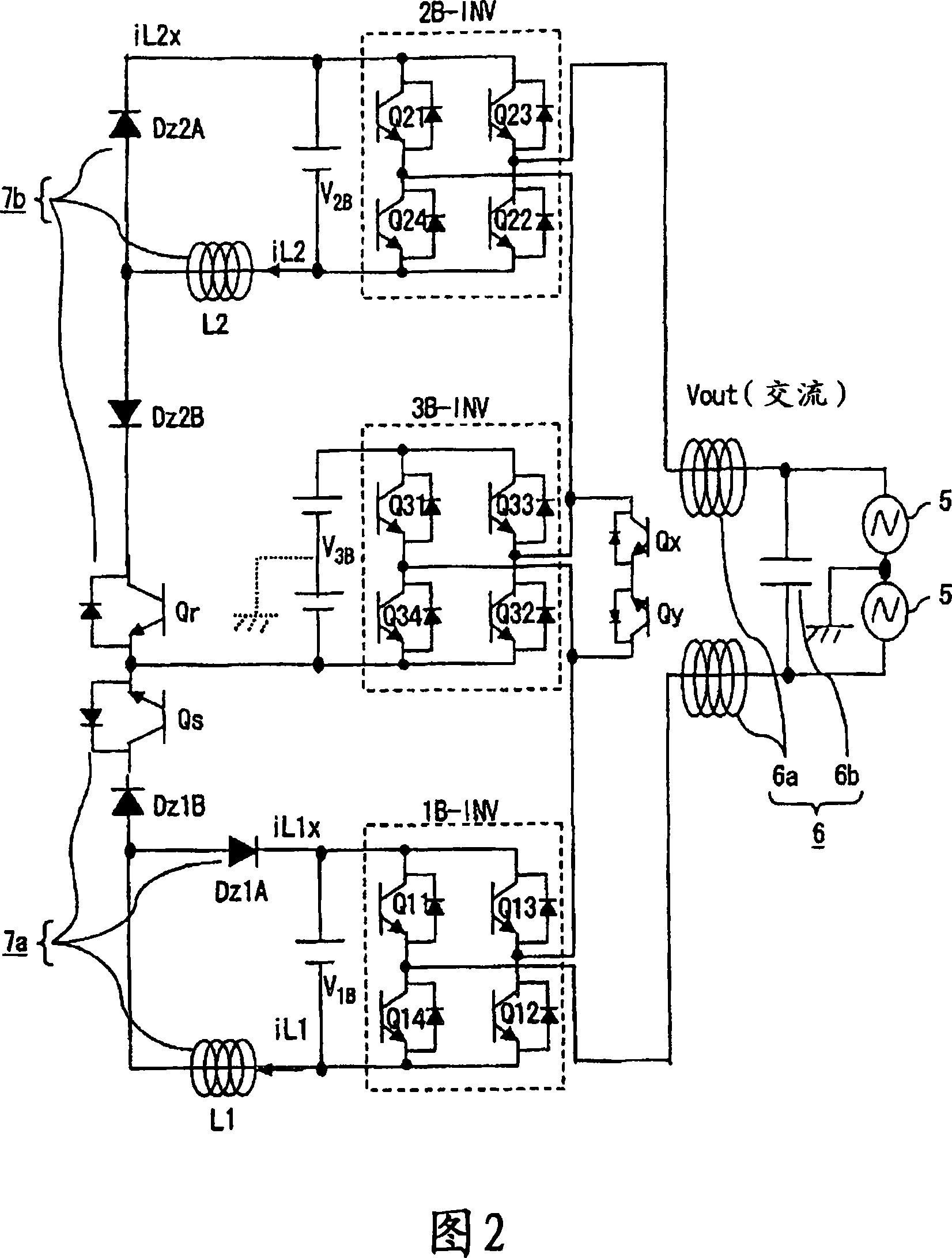
[0068] Next, a power conditioner according to Embodiment 2 of the present invention will be described below with reference to FIG. 4 . As shown in FIG. 4, the DC / DC converter 4 is constituted by chopper circuits 7a, 7b including reactors L1, L2, DC elements Dz1A, Dz2A, and switches Qs, Qr, as in Embodiment 1 above. In this embodiment, the reactors L1 and L2 of the chopper circuits 7 a and 7 b are magnetically coupled by the magnetic coupling core 100 made of a magnetic material.

[0069]In addition, the configuration other than the magnetic coupling of the reactors L1 and L2 is the same as that of the first embodiment described above. In addition, FIG. 4 omits illustration of the DC power supply 2 and the step-up chopper circuit 3 for convenience.

[0070] The operation will be described below.

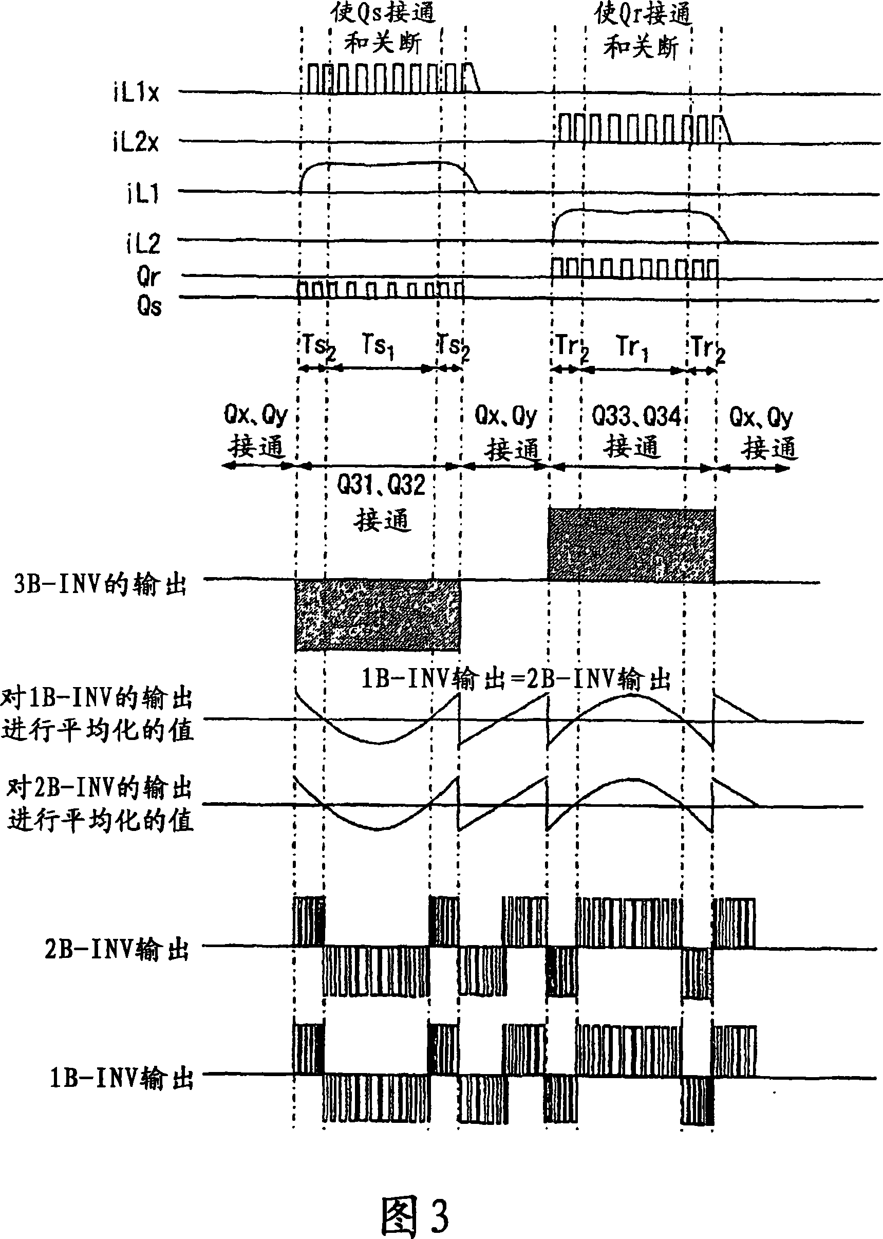
[0071] As shown in Embodiment 1 above, when the maximum single-phase inverter 3B-INV is a negative voltage output, the switch Qs of the chopper circuit 7a is turned on and off to su...

Embodiment approach 3

[0090] In Embodiments 1 and 2 above, the largest single-phase inverter 3B-INV is placed at the center, and the following shows how the input DC power supply V 1B , V 2B , V 3B The ascending order configuration of the voltage is the case.

[0091] Also in this case, the maximum DC supply V of the maximum single-phase inverter 3B-INV 3B It is to use the step-up chopper circuit 3 to the DC voltage V obtained in the DC power supply 2 based on solar energy as the 3rd DC power supply. O However, in FIG. 8 , for convenience, the DC power supply 2 and the step-up chopper circuit 3 are omitted. The voltage V of the DC power supply is controlled by the DC / DC converter 4 (see FIG. 1 ) so as to have a predetermined voltage ratio. 1B , V 2B , V 3B , here, assuming V 1B :V 2B :V 3B =1:3:9.

[0092]The DC / DC converter 4 is constituted by the chopper circuits 7a and 7b, and the DC power supply V 2B and DC supply V 1B connected between the chopper circuit 7a, at the maximum DC supp...


PUM


Abstract

A maximum single phase inverter (3B-INV) whose DC power supply voltage is the DC voltage V3B generated by stepping up a solar voltage by a step-up chopper circuit (3) is disposed at the central position, and single-phase inverters (2B-INV, 1B-INV) to which power is inputted from DC power supplies (V1B, V2B) supplied with power from the maximum DC power supply (V3B) are arranged on both sides of the maximum single phase inverter (3B-INV). The AC sides of the single phase inverters are connected in series, and the sum of the generated voltages of the single phase inverters is used as the output voltage, thus constituting a power conditioner. Chopper circuits (7a, 7b) are connected between the maximum DC power supply (V3B) and the DC power supplies (V1B, V2B), and power is supplied from the maximum DC power supply (V3B) to the DC power supplies (V1B, V2B) through switching elements in the single phase inverters.

Description

technical field [0001] The present invention relates to a power conversion device for converting DC power into AC power, and more particularly to a power conversion device used in a power conditioner or the like for connecting distributed power sources to a system. Background technique [0002] In a conventional power conditioner, for example, a solar power conditioner, a chopper is used to boost the voltage from a distributed power source that is a solar cell, and a PWM-controlled inverter is inserted in the subsequent stage. , occurs as an output AC voltage. [0003] The basic operation of such a conventional power conditioner is shown below. The DC power output from the solar cell drives the internal control power supply of the power conditioner, and the internal circuit can work. The internal circuit includes a chopper circuit and an inverter unit, and the chopper circuit boosts the voltage of the solar cell to the voltage required for connection to the system. The in...

Claims


Application Information

Patent Timeline
IPC IPC(8): H02M7/48H02M3/155H02M7/5387
CPCH02M7/5387H02M2001/0077H02M1/0077
Inventor 岩田明彦濑户诚山田正树原田茂树伊藤宽川上知之
Owner MITSUBISHI ELECTRIC CORP
Why Eureka
Try Eureka