Electric control device of textile machine

A control device and technology for textile machines, which are applied in electrical program control, speed reduction devices of AC motors, textiles and papermaking, etc., can solve the problems of large size, high power consumption and heavy weight of the device, and achieve small size, safe and reliable operation. , light weight effect

Inactive Publication Date: 2008-02-27
陆桂云
View PDF0 Cites 5 Cited by
  • Summary
  • Abstract
  • Description
  • Claims
  • Application Information

AI Technical Summary

Problems solved by technology

[0002] At present, the existing textile mechanical and electrical control devices are composed of traditional high-power

Method used


Image

  • Electric control device of textile machine
  • Electric control device of textile machine
  • Electric control device of textile machine

Examples


Embodiment Construction

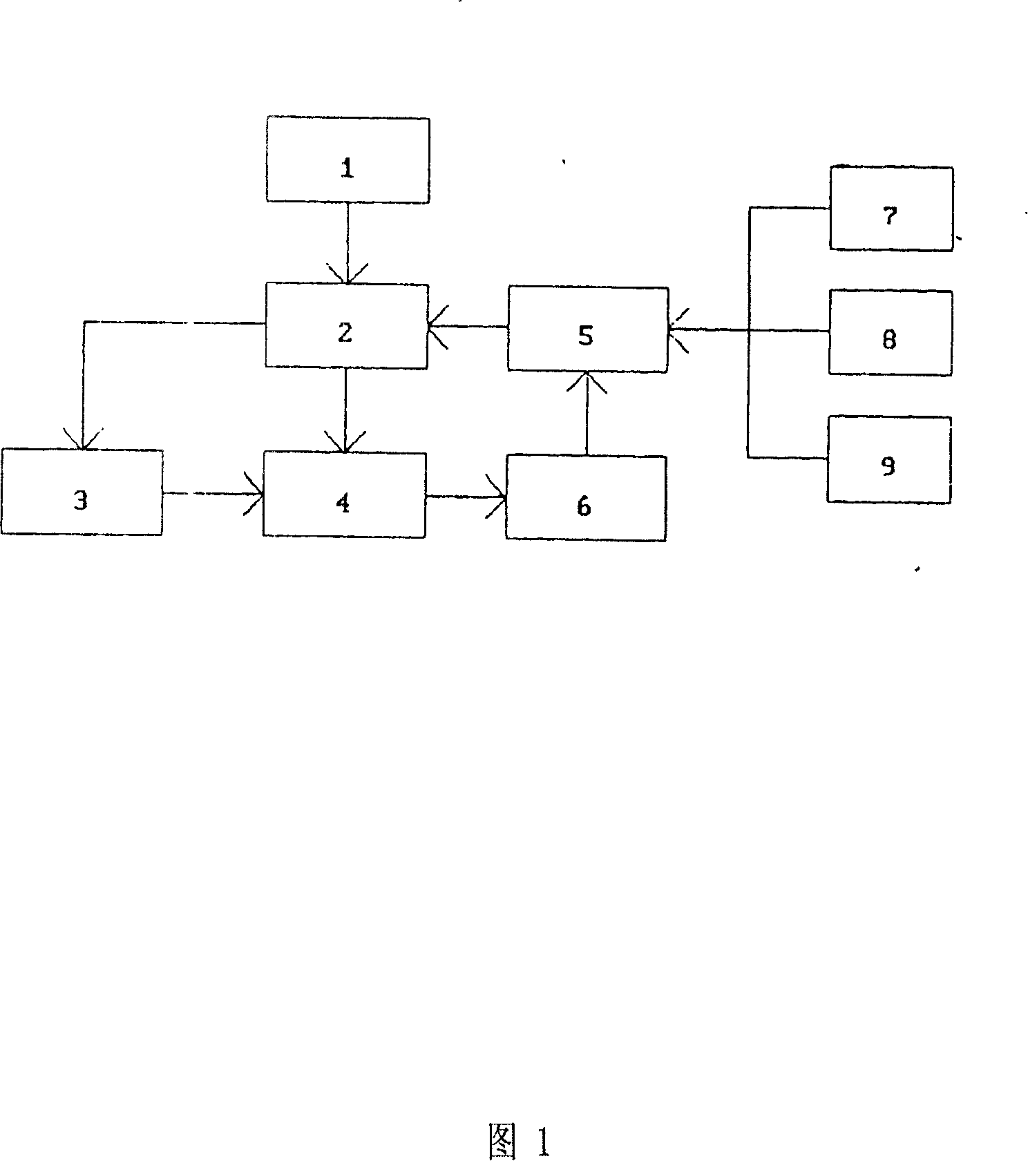
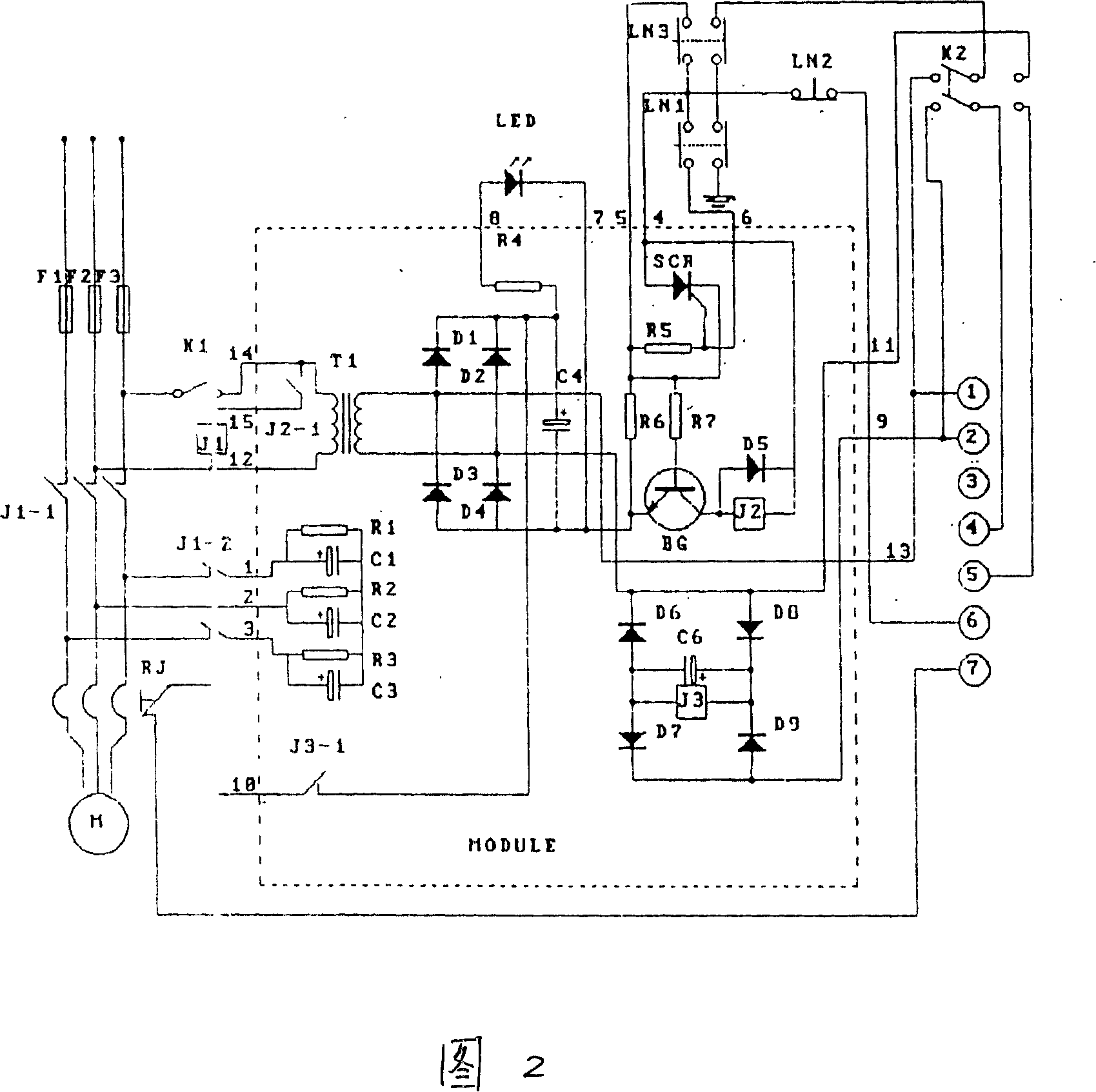
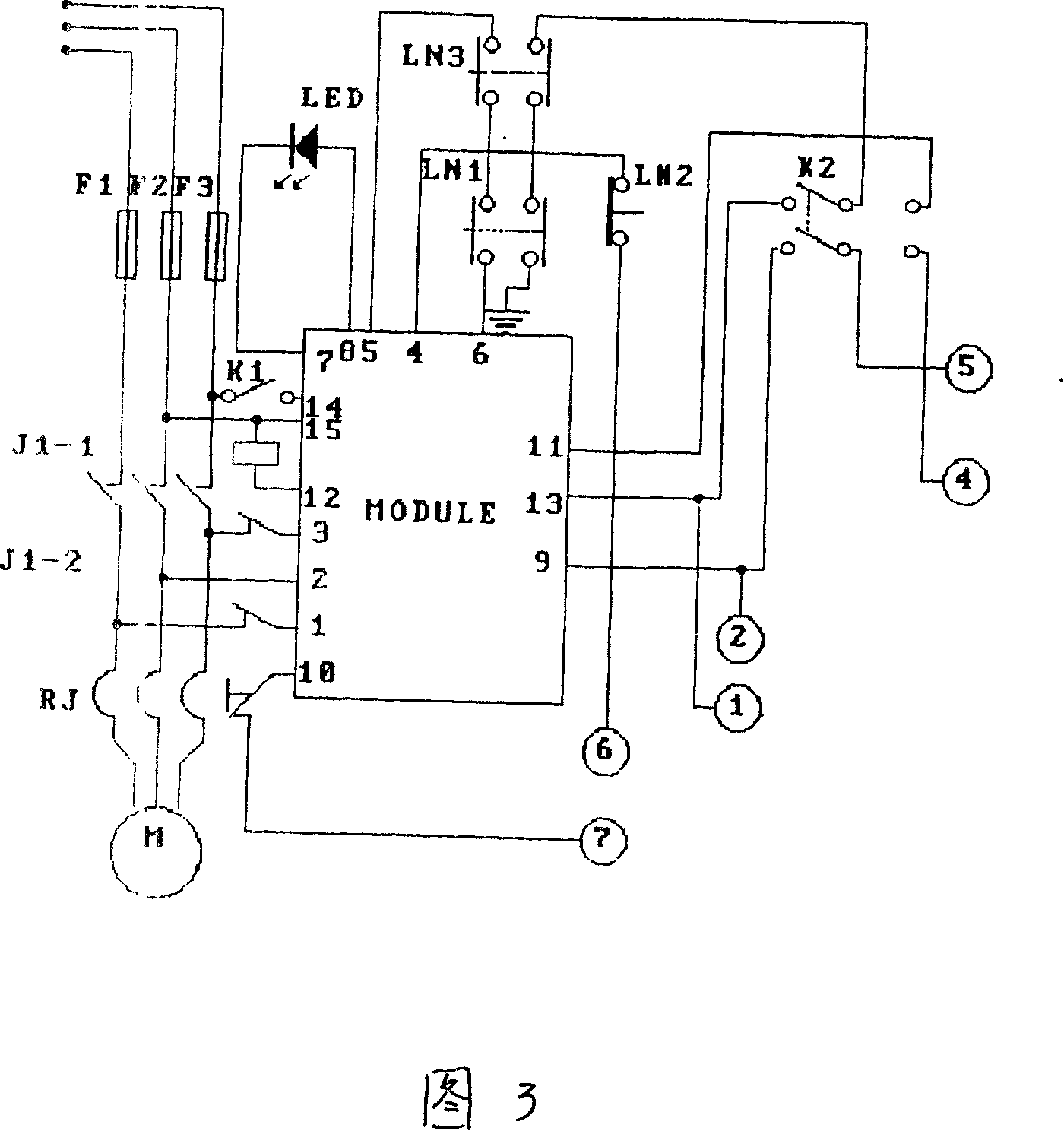
[0009] A textile electromechanical control device, characterized in that: the control device includes: a mains power supply (0), a main circuit (2), a brake circuit (3), a textile machine (4), a control circuit (5), and a protection circuit (6), start button (7), jog button (8), stop button (9). Among them, the mains power supply (1), the main circuit (2), and the textile machine (4) are connected sequentially; the main circuit (2), the braking circuit (3), the textile machine (4), the protection circuit (6), the control The circuit (5) is pressed into a closed circuit in series successively, and the start button (7), the point operation button (8), and the stop button (9) are connected with the control circuit (5) respectively. The main circuit (2) consists of three BLX type fuses (F1, F2, F3) respectively connected in series on the three-phase mains power line (1), and three normally open contacts J1-1 of the high-power electromagnetic relay J1 Composed of thermal relay RJ....


PUM


Abstract

The present invention discloses an electric control device of textile machine. Said control device includes the following several portions: power supply, main circuit, brake circuit, textile machine, control circuit, protection circuit, starting button and stopping button. Said invention also provides the connection mode of all the above-mentioned portions, and provides the working principle of said control device and its concrete operation method.

Description

technical field [0001] The invention relates to a textile electromechanical control device, in particular to a textile electromechanical control device that uses electronic technology to replace the original equipment electrical technology. technical background [0002] At present, the existing textile electromechanical control devices are composed of traditional high-power electromagnetic devices. The whole device is large in size, heavy in weight, consumes a lot of power, and is expensive. Contents of the invention [0003] The purpose of the present invention is to provide a textile electromechanical control device suitable for various circular knitting machines with small volume, light weight, simple and convenient installation and operation, safe and reliable operation, and energy saving. [0004] The specific solution of the present invention is: a textile electromechanical control device, characterized in that: the control device includes: mains power supply (0), ma...

Claims


Application Information

Patent Timeline
IPC IPC(8): D04B35/10D04B35/14G05B19/04H02P3/22
Inventor 陆桂云
Owner 陆桂云
Why Eureka
Try Eureka