Liquid crystal filling method and its special liquid crystal groove
A liquid crystal and tank technology, applied in instruments, nonlinear optics, optics, etc., can solve problems such as restricting production speed and low efficiency
- Summary
- Abstract
- Description
- Claims
- Application Information
AI Technical Summary
Problems solved by technology
Method used
Image
Examples
Embodiment Construction
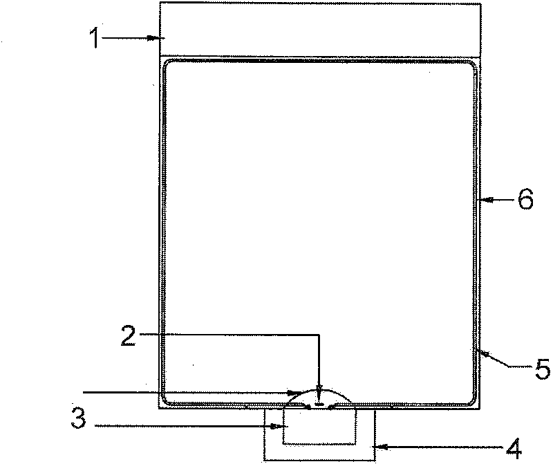
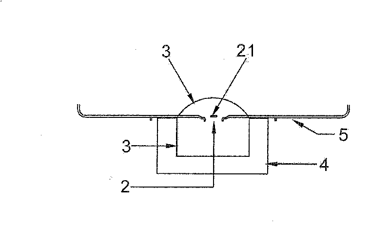
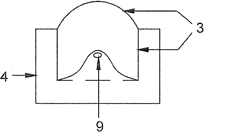
[0031] image 3 It is an improved liquid crystal cell with a heating device. The front view of the entire liquid crystal cell is no longer a regular rectangle, but has a bump at the bottom. A heater 9 is installed inside, which is used for heating after vacuuming and defoaming. liquid crystal. Figure 4 After the heater is turned on, the temperature distribution of the inside and outside of the liquid crystal is shown. From approaching the heater to the surface, the temperature of the liquid crystal decreases. Due to the effect of the cooling nitrogen on the surface, the temperature remains low in equilibrium to suppress volatilization. Figure 5 It is a schematic diagram of the improved liquid crystal perfusion. The liquid crystal cell is a very thin layer, about 1.0mm. The channels for blowing nitrogen are on both sides of the cell. Image 6 , Figure 7 Shown.
[0032] Since the sealing is deep into the liquid crystal surface, Figure 4 According to the temperature distribution ...
PUM
 Abstract
Description
Claims
Application Information
 - R&D
- Intellectual Property
- Life Sciences
- Materials
- Tech Scout
- Unparalleled Data Quality
- Higher Quality Content
- 60% Fewer Hallucinations
Browse by: Latest US Patents, China's latest patents, Technical Efficacy Thesaurus, Application Domain, Technology Topic, Popular Technical Reports.
© 2025 PatSnap. All rights reserved.Legal|Privacy policy|Modern Slavery Act Transparency Statement|Sitemap|About US| Contact US: help@patsnap.com


