
Method for manufacturing silicon block and silicon slice

A manufacturing method and technology for silicon wafers, applied in the directions of manufacturing tools, chemical instruments and methods, fine working devices, etc., can solve problems such as lower yield and substrate damage, and achieve the effect of finer surface roughness

Inactive Publication Date: 2008-02-27
MITSUBISHI ELECTRIC CORP
View PDF1 Cites 5 Cited by
  • Summary
  • Abstract
  • Description
  • Claims
  • Application Information

AI Technical Summary

Problems solved by technology

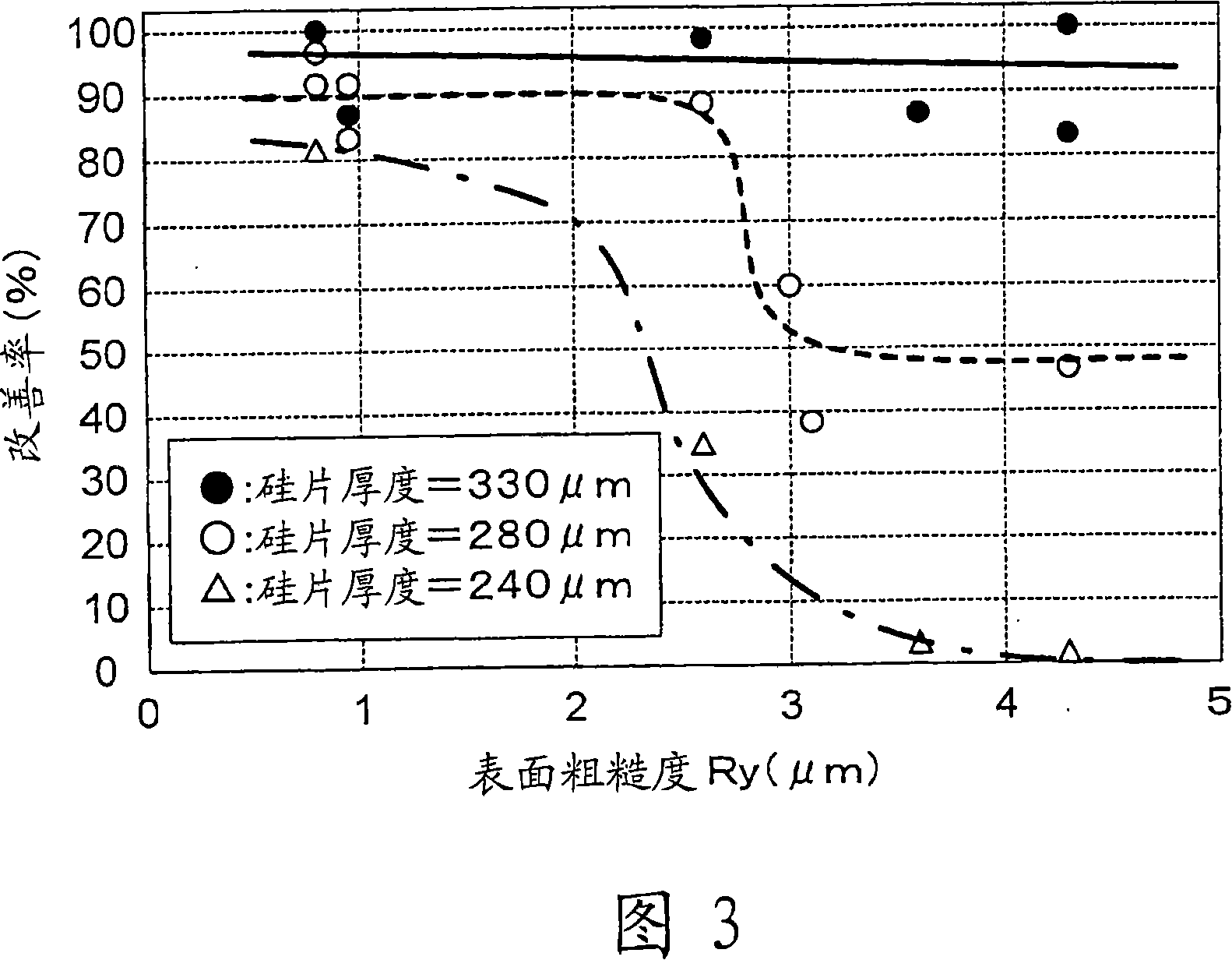
Next, as shown in the background art, even if the side surface of the silicon block is mechanically polished so that the surface roughness after polishing is 8 μm or less, the substrate will still be damaged when manufacturing a solar cell using a silicon wafer, and the yield may decrease. such a phenomenon

Method used


Image

  • Method for manufacturing silicon block and silicon slice
  • Method for manufacturing silicon block and silicon slice

Examples


Embodiment Construction

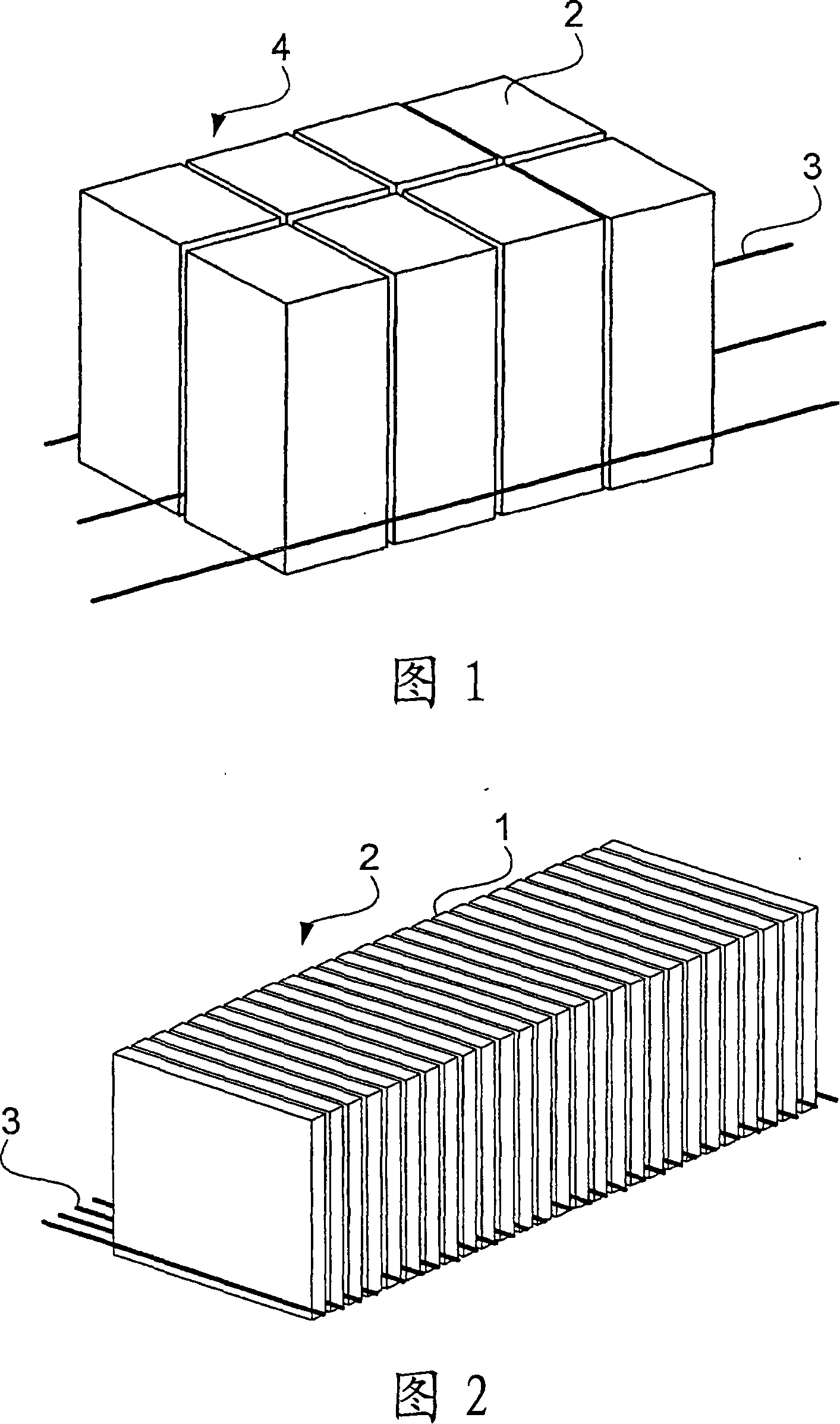
[0015] FIG. 1 is a diagram showing a state in which a silicon ingot is cut into silicon blocks in the present invention. Fig. 2 is a diagram showing a state in which a silicon block is cut into silicon wafers in the present invention.

[0016] The invention relates to the properties of semiconductor blocks in connection with the manufacture of semiconductor wafers of polycrystalline silicon for the manufacture of solar cells. Furthermore, silicon is generally widely used as a semiconductor, but gallium arsenide alloys, germanium, silicon carbide alloys, and the like can also be applied to the present invention.

[0017] In addition, in the following description, polysilicon will be described as an example.

[0018] As shown in FIG. 1 , a polycrystalline silicon ingot 4 is produced by dicing a polycrystalline silicon ingot 4 while supplying a silicon ingot dicing slurry to a dicing device. And the polycrystalline silicon block 2 is manufactured by cutting the polycrystalline ...


PUM


Abstract

The purpose is to provide a silicon block which can be processed into a thin silicon wafer having reduced breakage of a substrate during the manufacture of a solar battery. A method for producing a silicon block by cutting a silicon ingot using a silicon ingot cutting slurry containing abrasive grains and a basic substance, the basic substance being contained in a content of at least 3.5% by mass relative to the total mass of the liquid components of the slurry, the slurry containing an organic amine at a ratio of 0.5 to 5.0 inclusive by mass relative to the mass of the moisture in the liquid components of the slurry, and the slurry having a pH of 12 or higher and being used at a temperature within the range from 65 to 95 DEG C.

Description

technical field [0001] The present invention relates to a silicon ingot manufacturing method for manufacturing a silicon ingot from a polycrystalline silicon ingot used to manufacture a silicon wafer for a solar cell, and a silicon ingot manufacturing method for manufacturing a silicon wafer using the silicon ingot manufactured by the manufacturing method. Background technique [0002] Polycrystalline silicon wafers used in the manufacture of solar cells are manufactured by manufacturing a rectangular prism-shaped polycrystalline silicon ingot, cutting out a plurality of rectangular prism-shaped polycrystalline silicon blocks from the polycrystalline silicon ingot with a band saw, and then cutting the polycrystalline silicon block into quadrangular shapes. plate. [0003] When a silicon block is cut out from a silicon ingot, if a band saw is used, the surface of the block may be damaged, and if a silicon wafer is manufactured without removing the damaged portion, cracks will...

Claims


Application Information

Patent Timeline
IPC IPC(8): B28D5/04C09K3/14
Inventor 森川浩昭唐木田昇市河嵜贵文
Owner MITSUBISHI ELECTRIC CORP
Learn More