Method for producing a target

A manufacturing method and gas technology, applied in the field of sputtering targets

Inactive Publication Date: 2008-02-27
ULVAC INC
View PDF1 Cites 1 Cited by
  • Summary
  • Abstract
  • Description
  • Claims
  • Application Information

AI Technical Summary

Problems solved by technology

[0009] This invention is made to solve the problems that arise when manufacturing targets by melting the main material with additives, and provides a technology that can manufacture target constituent materials without using a large vacuum chamber

Method used


Image

  • Method for producing a target

Examples


Embodiment Construction

[0041] The manufacturing method of the sputtering target of this invention is demonstrated.

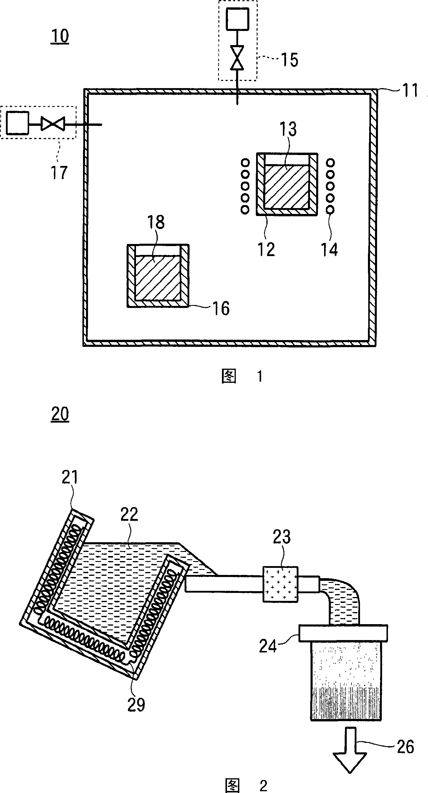
[0042] Reference numeral 10 in FIG. 1 is a primary melting device, which has a vacuum tank 11 . A primary melting crucible 12 is disposed inside the vacuum chamber 11 . In addition, an inert gas introduction system 15 and a vacuum exhaust system 17 are connected to the vacuum tank 11 .

[0043] First, the main material (here, aluminum: Al) and additives (here, cerium: Ce) are charged into the inside of the primary melting crucible 12 in a predetermined ratio, and the inside of the vacuum chamber 11 is vacuumed by the vacuum exhaust system 17. Exhaust until the pressure is below 1Pa.

[0044] Then, an inert gas (herein referred to as argon) is introduced into the inside of the vacuum tank 11 from the inert gas introduction system 15, and the inside of the vacuum tank 11 is boosted to 2600 Pa, which is lower than the atmospheric pressure, forming a primary ambient gas with low oxygen ...


PUM


Abstract

The present invention safely adds additives that are easy to catch fire in the atmosphere to make targets cheaply. In the low-oxygen atmosphere, additives are added to the main material to form the primary alloy 13 in the molten state, and the main material is added to the molten primary alloy 13 in the atmospheric environment to make a secondary alloy. The primary alloys 13, 18 in molten or solid state are stable and therefore do not ignite in the atmosphere. The amount of the primary alloys 13 and 18 is smaller than that of the secondary alloy, so the vacuum chamber 11 for forming the primary atmosphere gas should only be small.

Description

technical field [0001] The present invention relates to the technical field of sputtering targets, in particular to the manufacturing technology of targets with additives added to main materials such as aluminum. Background technique [0002] In some cases, an Al target or an Al alloy target is used to produce a thin film for wiring or a reflective film. [0003] In a thin film using a conventional Al target, if the temperature of the thin film rises during annealing, Al crystal grains grow, and foreign matter called hillocks are generated on the Al surface. When a thin film having such protrusions is etched to form a wiring film, the shape pattern of the wiring film is disturbed. In addition, when producing a reflective film, since foreign matter exists on the surface of the film, light is diffusely reflected and becomes cloudy with low reflectance. [0004] In order to prevent the above phenomenon from happening, there are Al alloy targets with additives added to Al, but...

Claims


Application Information

Patent Timeline
Patent Type & Authority Applications(China)
IPC IPC(8): C23C14/34H01L21/285C22C1/02
CPCC23C14/3414C22C1/026C23C14/34C22C1/02C23C14/14C22C21/00H01L21/203
Inventor 太田淳杉浦功谷典明松本昌弘片桐弘明增田忠石桥晓伊藤隆治
Owner ULVAC INC
Why Eureka
Try Eureka