Multilayer coil

A technology of stacking coils and coils, which is applied in transformers/inductor coils/windings/connections, electrical components, printed inductors, etc., and can solve problems such as different linear expansion coefficients, interlayer peeling, cracks, etc.

Inactive Publication Date: 2010-11-03
MURATA MFG CO LTD
View PDF4 Cites 2 Cited by
  • Summary
  • Abstract
  • Description
  • Claims
  • Application Information

AI Technical Summary

Problems solved by technology

[0004] However, in the open magnetic circuit type laminated coil, there is a problem that a structural defect occurs
That is, the magnetic layer 51 and the non-magnetic layer 53 have different linear expansion coefficients due to their different material compositions. With an expansion coefficient of 55, structural defects such as delamination or cracks will occur
In addition, if the non-magnetic layer is formed very thin in order to obtain a high inductance value, such a problem becomes more obvious.

Method used


Image

  • Multilayer coil
  • Multilayer coil
  • Multilayer coil

Examples


Embodiment 1

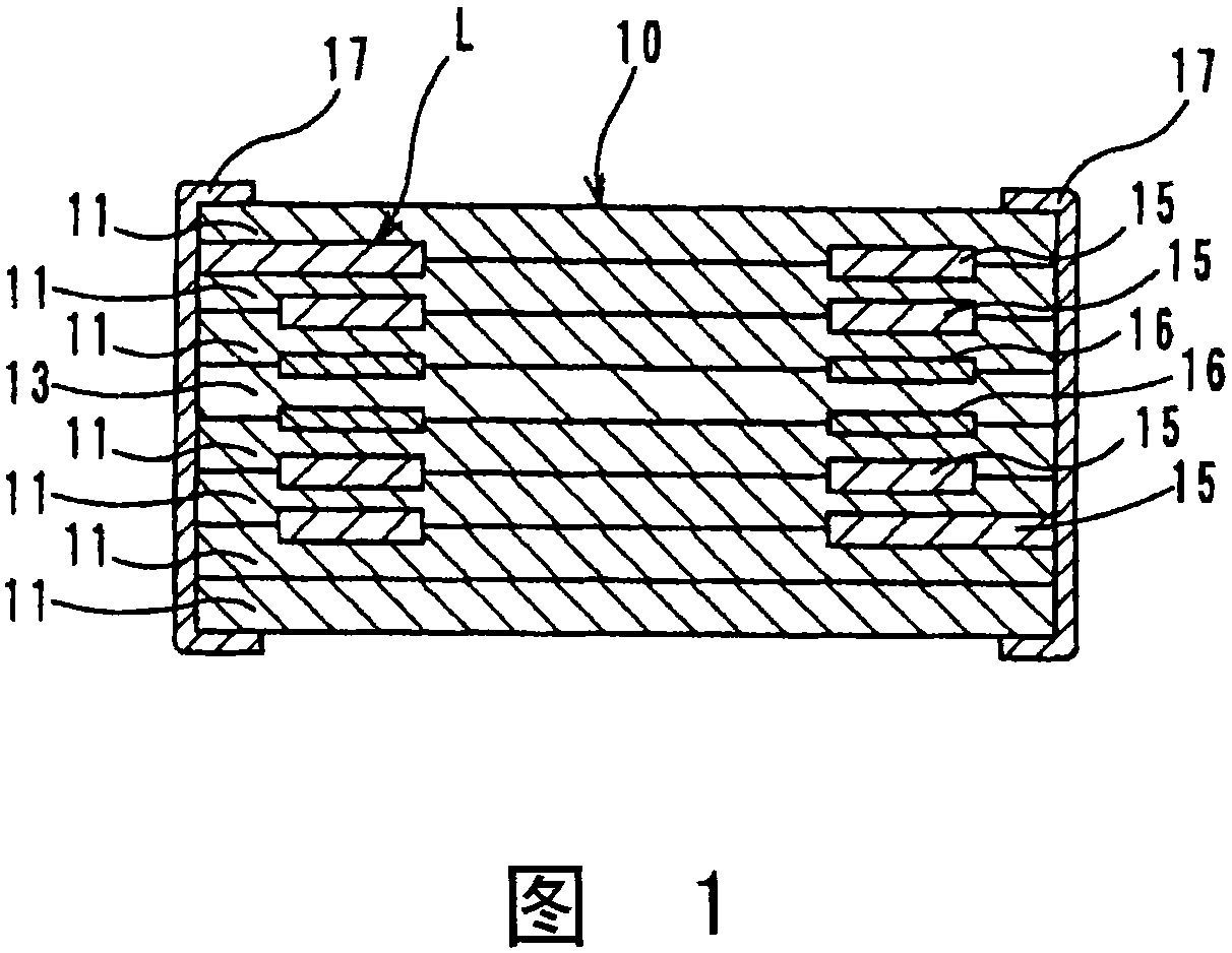
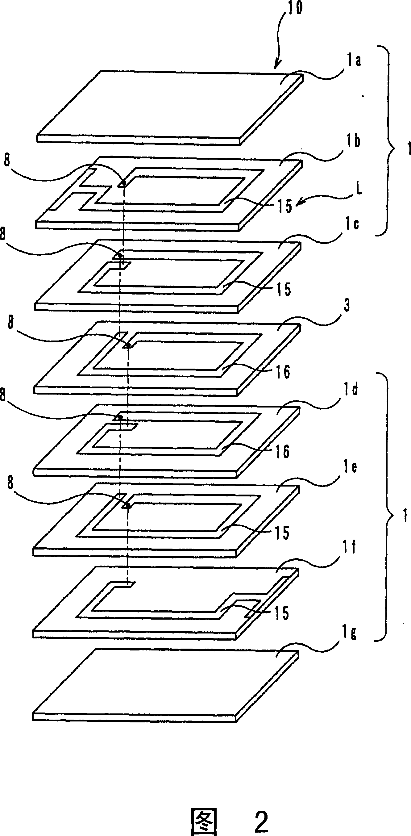
[0018] figure 1 It is a schematic sectional view of the laminated coil in the first embodiment of the present invention. The laminated coil includes: a laminated body 10 composed of a plurality of magnetic layers 11 and non-magnetic layers 13, a coil L formed by spirally connecting coil conductors 15 and 16 formed in the laminated body 10, and an external electrode 17 and 17. In addition, the magnetic layer 11 is formed on both main surfaces of the nonmagnetic layer 13 .

[0019] Such as figure 1 As shown, the coil conductor 16 located on both main surfaces of the nonmagnetic layer 13 is thinner than the coil conductor 15 having a predetermined thickness not located on both main surfaces of the nonmagnetic layer 13 . Specifically, it is less than 0.6 times the thickness of the magnetic layer 11 and the thickness of the nonmagnetic layer 13, and is thicker than 0.1 times the thickness of the coil conductor 15 that is not located on both main surfaces of the nonmagnetic lay...

Embodiment 2

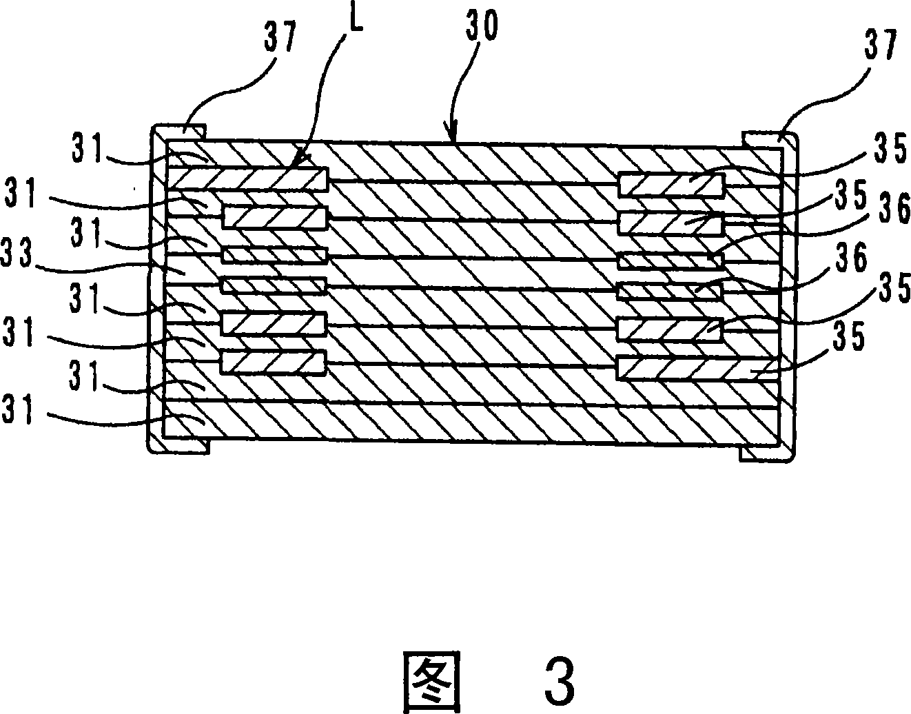
[0038] image 3 It is a schematic sectional view of the laminated coil in the second embodiment of the present invention. In addition, in image 3 in, for with figure 1 For the same or corresponding parts, descriptions are appropriately omitted.

[0039] Such as image 3 As shown, the laminated coil includes a laminated body 30 formed by forming a plurality of magnetic layers 31 on both main surfaces of a non-magnetic layer 33, and is formed by connecting coil conductors 35 and 36 formed in the laminated body 30 in a spiral shape. The coil L, and the external electrodes 37 and 37. Then, the thickness of the coil conductor 36 located on both main surfaces of the non-magnetic material layer 33 is thinner than the other coil conductor 35 having a predetermined thickness which is not located on both main surfaces of the non-magnetic material layer 33 . Specifically, the thickness of the coil conductor 36 positioned on both main surfaces of the nonmagnetic layer 33 is less th...


PUM

PropertyMeasurementUnit
thicknessaaaaaaaaaa

Abstract

An open magnetic circuit type multilayer coil free from a structural defect such as interlayer separation or cracking. On both major surfaces of a nonmagnetic layer (13) are provided a layered body (10) where magnetic layers (11) are formed and a coil (L) where coil conductors (15, 16) that are formed on the layered body (10) and have a specified thickness are spirally interconnected. The coil conductor (16), out of the coil conductors (15, 16) formed in the layered body (10), located on the major surface of the nonmagnetic layer (13) has a small thickness that is not greater than 0.6 times those of the magnetic layer (11) and the nonmagnetic layer (13) but is greater than 0.1 times that of the coil conductor (15) not located on the major surface of the nonmagnetic layer (13).

Description

technical field [0001] The present invention relates to a laminated coil, in particular to an open magnetic circuit type laminated coil with excellent DC superposition characteristics. Background technique [0002] There is an open magnetic circuit type laminated coil described in Patent Document 1 for the purpose of preventing magnetic saturation from occurring in the magnetic body due to direct current and rapidly reducing the inductance value. Such as Figure 5 As shown, the open magnetic circuit type laminated coil is formed by forming a laminated body 50 in which a plurality of magnetic layers 51 are formed on both main surfaces of a non-magnetic layer 53, and coil conductors 55 formed in the laminated body 50 are connected in a spiral shape. The formed coil L and the external electrodes 57 and 57 formed on both end surfaces of the laminated body 50 are formed. In the open magnetic circuit type laminated coil, since the magnetic flux leaks from the non-magnetic layer 5...

Claims


Application Information

Patent Timeline
Patent Type & Authority Patents(China)
IPC IPC(8): H01F17/00H01F27/28
CPCH01F2017/002H01F27/292H01F17/0013H01F27/00H01F27/28
Inventor 都筑庆一
Owner MURATA MFG CO LTD
Why Eureka
Try Eureka