Bandage type wine bottle burglar preventor and special unlocking device

An anti-theft device and unlocker technology, which is applied to building locks, lock applications, and non-mechanical transmission-operated locks, can solve the problems of troublesome injection molding, high cost, and high processing cost of lock cylinders, and achieves a release method that saves labor and produces The effect of low cost and high production efficiency

Inactive Publication Date: 2008-03-05
SHENZHEN RONGHUA ELECTRONICS
0 Cites 3 Cited by

AI-Extracted Technical Summary

Problems solved by technology

However, there is a metal part on the strap lock post of this wine bottle anti-theft device. The processing cost of this metal part is relatively high, and the injection molding of the lock post is also troublesome, with low efficiency and high cost.
Like the above-mentioned steel wire rope strap wine bottle anti-theft device, the strap tail is exposed, and the induction coil needs to be placed in another cavit...

Method used

The EAS anti-theft label 3 of different frequencies can be installed in the housing, and the scope of application is wide.
[0030] The upper shell 1, the lower sh...

Abstract

The present invention is one kind of strap type anti-theft device for wine bottle and its special unlocking unit. The anti-theft device includes one casing, one strap connected to the casing, and anti-theft EAS label inside the casing. The casing is provided with one strap port for the free end of the strap to pass through, one strap backstop comprising one locking block and one spring, and one unlocking hole for the unlocking unit to be inserted in. The unlocking unit includes one shell, one notch for holding the casing of the anti-theft device, and one shifting fork. The special unlocking unit can unlock the strap type anti-theft device easily and reliably.

Application Domain

Locks for portable objectsNon-mechanical controls

Technology Topic

BandageAnti theft +3

Image

  • Bandage type wine bottle burglar preventor and special unlocking device
  • Bandage type wine bottle burglar preventor and special unlocking device
  • Bandage type wine bottle burglar preventor and special unlocking device

Examples

  • Experimental program(1)

Example Embodiment

[0024] This will be further explained below in conjunction with the drawings.
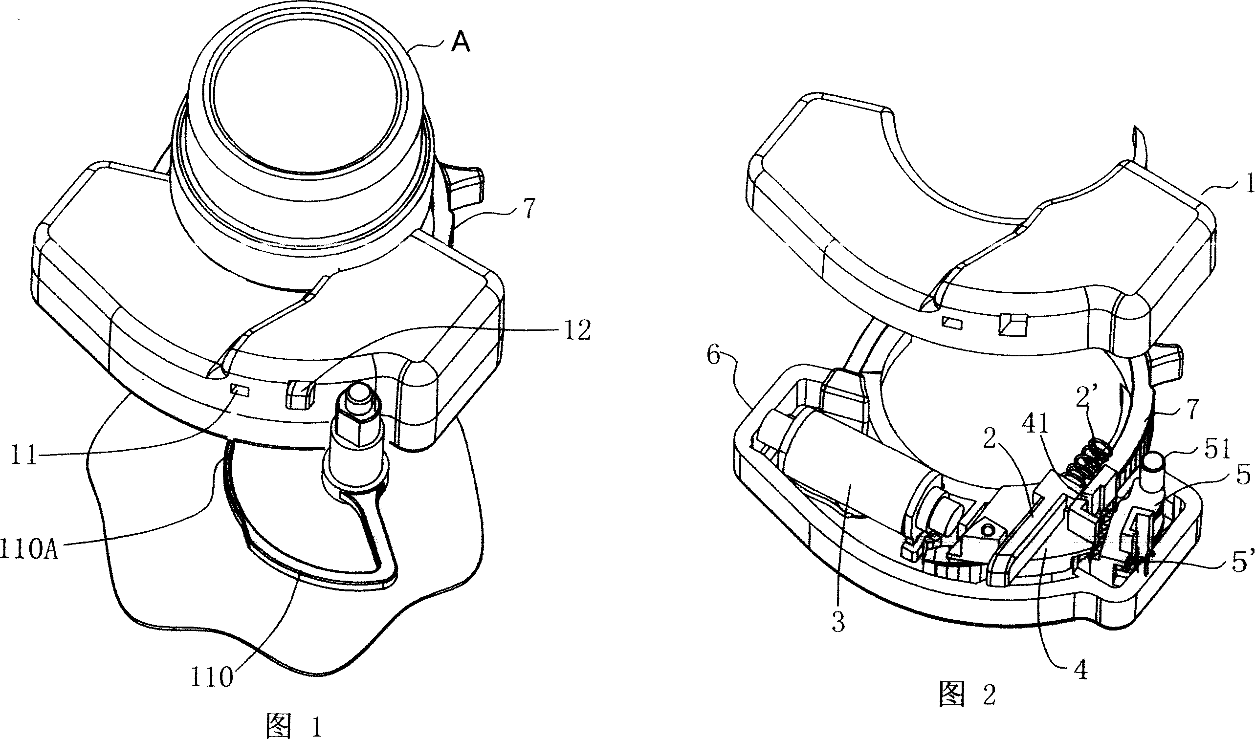
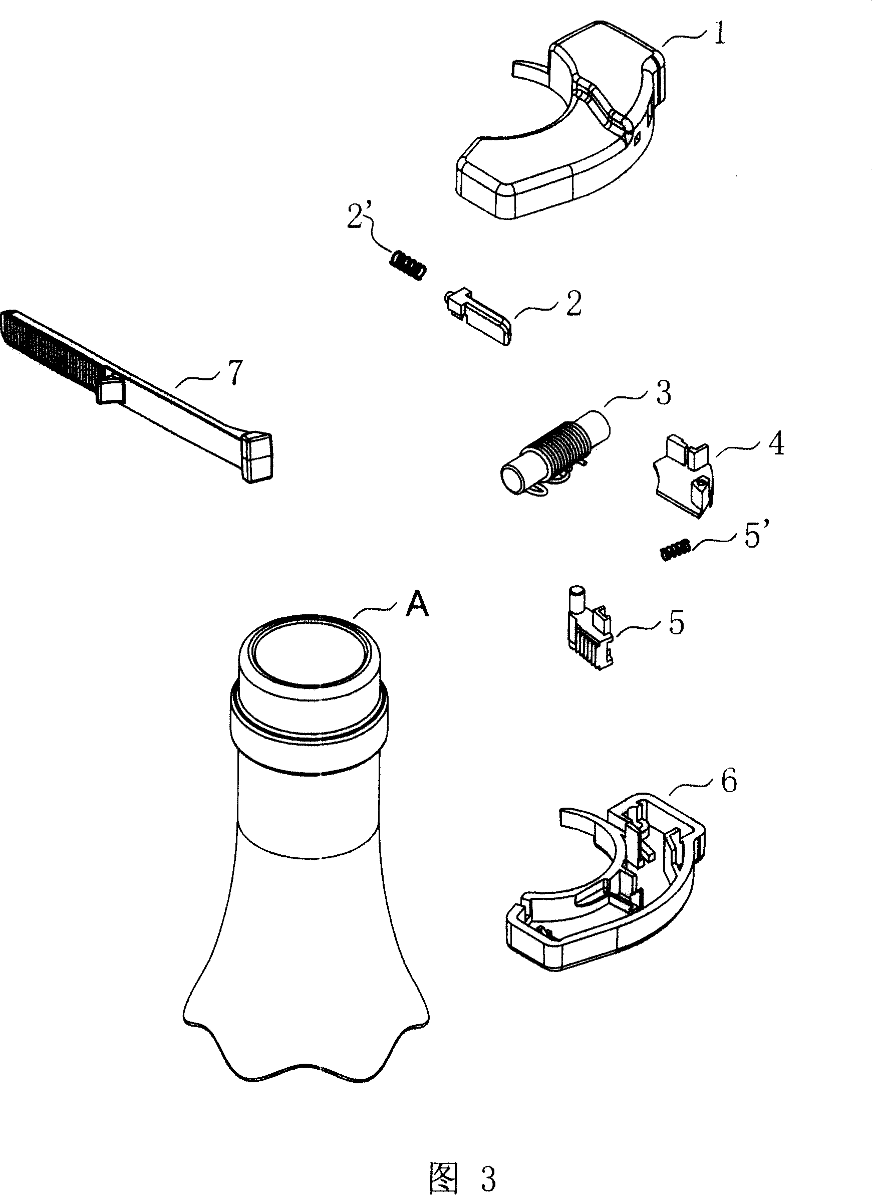
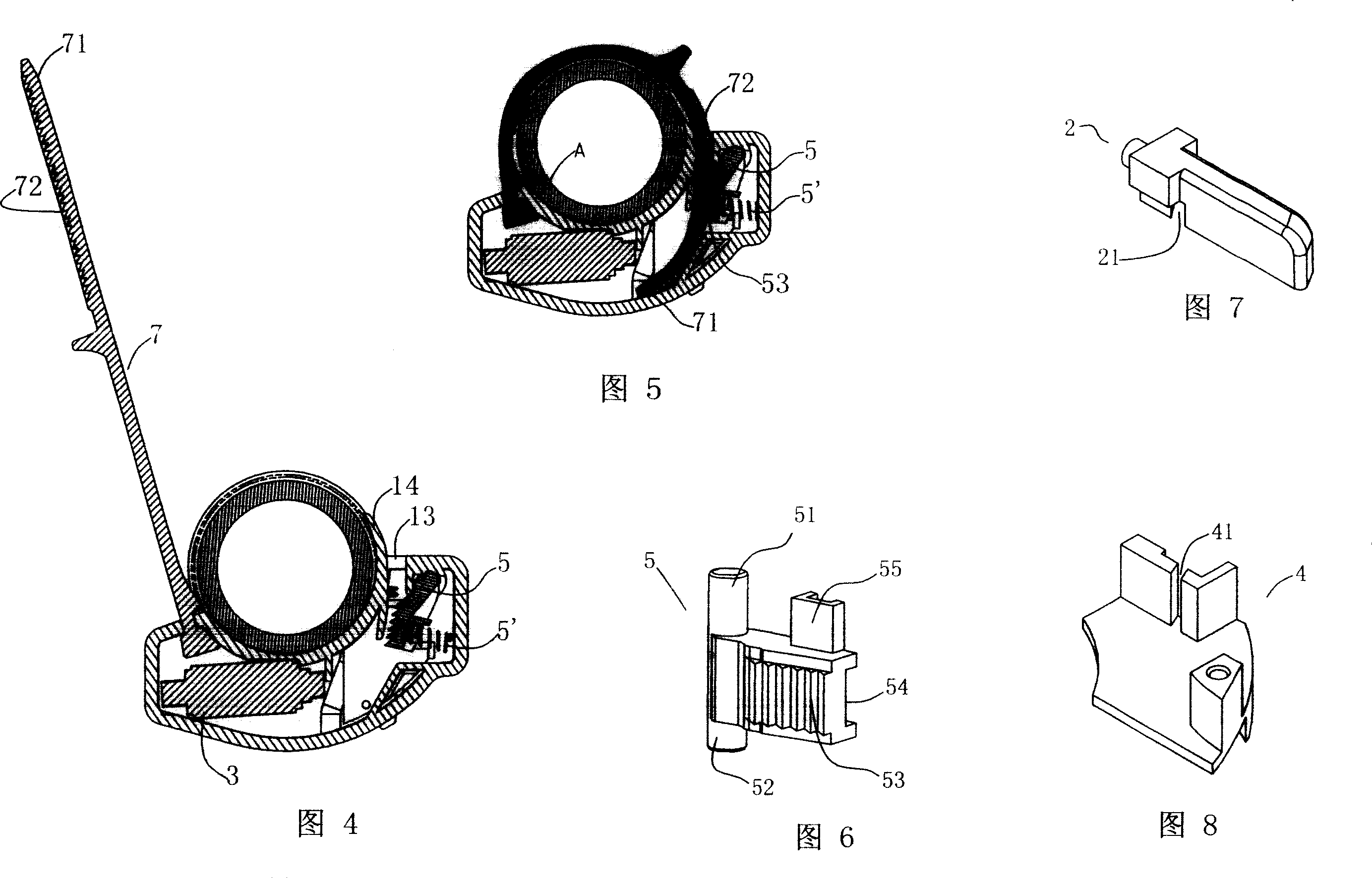
[0025] As shown in Figures 1-8, the strap type wine bottle anti-theft device includes a shell composed of an upper shell 1 and a lower shell 6, a strap 7, and an EAS anti-theft tag 3 (ie Electromagnetic coil), one end of the strap 7 is connected to the shell, the upper shell 1 and the lower shell 6 are ultrasonically welded together, the shell is provided with a strap inlet and outlet 13 for the free end 71 of the strap to enter and exit, inside the shell A strap anti-reversal device is provided near the strap entrance and exit 13, which includes a self-locking pendulum block 5. The upper and lower sides of one end of the self-locking pendulum block 5 are respectively provided with an upper pivot 51 and a lower pivot 52 , The self-locking pendulum block 5 is provided with a convex block 55 on the upper side of the other end. The convex block 55 is used for the shifting fork of the unlocker. The upper and lower pivots 51 and 52 of the self-locking pendulum block 5 are connected to the upper shell 1 and The lower shell 6 is pivotally connected, the front side of the self-locking pendulum block 5 (that is, the side in contact with the strap 7) is provided with locking teeth 53, and the back 54 of the self-locking pendulum block 5 is provided with a spring installation position, which is connected to A self-locking pendulum spring 5'is arranged between the shells, and the side wall of the upper shell 1 is provided with an unlocking hole 11 for entering and exiting the fork of the unlocker. When in use, the free end 71 of the strap is inserted into the casing from the strap inlet and outlet 13 around the bottleneck A until the bottleneck A is tightened. Under the action of the self-locking pendulum spring 5', the locking teeth 53 of the self-locking pendulum block 5 It meshes with the teeth 72 on the strap 7 to prevent the free end 71 of the strap from exiting the housing, thereby locking the EAS anti-theft label 3 on the wine bottle, achieving the purpose of anti-theft.
[0026] It also includes an anti-theft opening device, which is installed on the side of the lock tooth 53 of the self-locking pendulum block 5 in the housing. It includes a movable block 2 and a fixed block 4, the movable block 2 and the fixed block The block 4 is respectively provided with a first key port 21 and a second key port 41, the movable stop 2 is installed on the fixed stop 4, the movable stop 2 is elongated, and its inner end is provided with a convex post 22, the movable stop The first key port 21 on the 2 is a downward gap, the second key port 41 on the fixed stop 4 is an upward gap, the first key port 21 and the second key port 41 are located on the same horizontal plane, and the movable block A stop spring 2'is installed on the boss 22 at the inner end of the block 2, and the other end of the stop spring 2'is pressed against the rear side of the housing. The front end 23 of the movable stop 2 passes through the through hole 12 on the housing and is exposed to the outside of the housing. Among them, the second key port 41 on the fixed block 4 is always located on the unlocking track of the unlocker fork, while the first key port 21 on the movable block 2 is usually not on the unlocking track of the unlocker fork. The unlocker can push the movable block 2 to the correct position, so that the first key port 21 and the second key port 41 coincide. The shift fork of the special unlocker passes through the two key ports 21 and 41 to move the self-locking pendulum block 6 Rotate to make the free end 71 of the strap fall out of the shell.
[0027] The following is an analysis of the locking principle of the strap in conjunction with Figures 4 and 5. Figure 4 is a cross-sectional view of the strap after it is loosened. It can be seen from the figure that when the free end 71 of the strap is released, the self-locking pendulum block 5 moves along its pivots 51, 52 under the action of the pendulum block spring 5'. Turn the clock hand until the self-locking pendulum block 5 abuts on the ribs of the upper and lower shells. When the wine bottle is to be tightened, the strap 7 is passed around the bottleneck A of the wine bottle, and the free end 71 of the strap extends into the casing from the strap inlet and outlet 13. When extending, the oblique side of the tooth 72 on the strap 7 is in contact with the oblique side of the locking tooth 53 of the self-locking pendulum block 5, and the self-locking pendulum block 5 is subjected to a counterclockwise direction along the pivots 51 and 52 of the self-locking pendulum block. Moment, this moment overcomes the spring force of the pendulum spring 5', the self-locking pendulum 5 rotates counterclockwise, and the free end 71 of the strap can be smoothly extended into the housing. FIG. 5 is a cross-sectional view of the strap after it is tightened. As shown in the figure, at this time, the right-angle side of the teeth 72 on the strap 7 is in contact with the right-angle side of the lock tooth 53 of the self-locking pendulum block. When the strap 7 is pulled out by force, the right-angle side of the locking teeth 53 of the self-locking pendulum block 5 receives an outward force, so that the self-locking pendulum block 5 receives a clockwise moment, which makes the self-locking pendulum block 5 The strap 7 is pressed tightly, and the direction of the torque is just opposite to the disengagement direction of the self-locking pendulum block 5, so that the strap 7 is locked by the self-locking pendulum block 5.
[0028] The side of the shell in contact with the bottle neck A of the wine bottle is a concave solitary surface, and the concave solitary surface has a concave solitary section 14 extending outward at one end of the belt inlet and outlet 13. These special structures can make this product adapt to different bottlenecks of different sizes, and combined with adjusting the length of the free end 71 of the strap inserted into the shell, this product can tighten and prevent theft of wine bottles with different bottlenecks.
[0029] EAS anti-theft tags 3 of different frequencies can be installed in the shell, which has a wide range of applications.
[0030] The upper shell 1, the lower shell 6, the self-locking pendulum block 5, the movable block 2, the fixed block 4 are all made of plastic injection molding, and the processing cost is low.
[0031] As shown in Figures 9-13, the unlocker of the above wine bottle anti-theft device includes a shell composed of an upper shell 101 and a lower shell 108. The surface of the lower shell 108 has a cavity 108A that matches the upper shell 1 of the wine bottle anti-theft device. A pair of bearings 114 and 109 are installed in the upper shell 101 and the lower shell 108. The shift fork 110 is pivotally connected between the pair of bearings 114 and 109. A gear 113 is installed on the pivot 110B of the shift fork 110. One side of the pivot 110B A rack 102 is provided. The rack 102 meshes with the gear 113. One end of the rack 102 extends out of the housing composed of the upper shell 101 and the lower shell 108. When the rack 102 moves, it drives the gear 113 and the shift fork 110 to rotate. The lower shell 108 of the housing is provided with a fork through hole 108B.
[0032] An EAS anti-theft tag 112 is installed in the lower shell 108 of the unlocker housing to prevent the unlocker from being taken out of the EAS system without permission.
[0033]A rack rail 108D is arranged in the lower shell 108 of the unlocker, the rack 102 is installed in the rack rail 108D, and a rack return spring 106 is arranged between the rack 102 and the lower shell 108. One end of the rack return spring 106 is fixed to the lower shell 108 with screws, and the other end is connected to the rack 102. After the cashier releases the rack 102 after unlocking, the rack return spring 106 drives the rack 102, the gear 113, and the shift fork 110 to return.
[0034] A movable stop driving part 108C is provided on the surface of the lower shell 108 for accommodating the side wall of the cavity 108A of the upper case 1 of the wine bottle anti-theft device. The movable stop driving portion 108C is used to drive the movable stop 2 of the wine bottle anti-theft device. Move so that the first key port 21 on the movable block 2 and the second key port 41 on the fixed block 4 coincide. When the upper casing 1 of the wine bottle anti-theft device is embedded in the cavity 108A on the surface of the lower casing 108 of the lock opener, the movable stop driving part 108C positions the movable stop 2 of the wine bottle anti-theft device in a position so that the movable stop 2 is The first key port 21 on the fixed stop 4 coincides with the second key port 41, and then the rack 102 of the unlocker is pushed by hand to drive the gear 113 and the shift fork 110 to rotate, so that the shift fork head 110A passes through the unlocker in turn The fork through hole 108B of the lower cover 108, the unlocking hole 11 of the upper case 1 of the anti-theft device, the first key port 21 in the middle of the movable block 2 of the anti-theft device, the second key port 41 on the fixed block 4, and finally act on the self Lock the face 55 of the pendulum block 5, so as to turn the self-locking pendulum block 5 to rotate counterclockwise, the lock teeth 53 of the self-locking pendulum block 5 and the teeth 72 on the strap 7 are separated, the strap 7 comes out, and the anti-theft device is released. After the strap is released, the cashier releases the rack 102 of the unlocker, and the rack 102, gear 113, and shift fork 110 of the unlocker return to their positions. The anti-theft device can be removed from the unlocking device.
[0035] The unlocker also includes a lock head 105, which is mounted on the lower shell 108 of the lock unlocker. The lock head 105 is installed in the lower shell 108 with a locking block 104, and the rack 102 is provided with the locking block Block 104 matches the gear 102A. When the cashier uses the key of the unlocking device to open the lock 105, the locking block 104 rotates 90° to disengage from the rack 102, and the rack 102 can slide back and forth along the guide rail 108D to work. The chain 107 is used to connect the unlocking device to the cash register to prevent other personnel from opening the anti-theft device on the cash register.
[0036] The position of the movable block 2 in the above-mentioned wine bottle anti-theft device is the key to the anti-theft opening. When the unlocker is not placed on the anti-theft device, the movable block 2 is under the action of the block spring 2', and the convex block 2 on the movable block 2 The output part is close to the end face of the rib in the upper shell 1 (not shown). At this time, the first key opening 21 on the movable stop 2 and the second key opening 41 on the fixed stop 4 are misaligned, what Objects can't get in, which means that the self-locking pendulum 5 cannot be touched by other methods. When the movable block 2 is pushed back to the end, the first key port 21 on the movable block 2 and the second key port 41 on the fixed block 4 are also misaligned, and the self-locking pendulum block 5 is not touched at this time. . Only when the unlocking device is put on the anti-theft device, the movable block driving part 108C on the unlocking device can push the movable block 2 to the set correct position, so that the first key port 21 on the movable block 2 and the fixed block The second key port 41 on 4 will be aligned. Only in this case can the fork 110 of the unlocker reach the self-locking pendulum block 5 of the anti-theft device, and the strap 7 can be released.

PUM

no PUM

Description & Claims & Application Information

We can also present the details of the Description, Claims and Application information to help users get a comprehensive understanding of the technical details of the patent, such as background art, summary of invention, brief description of drawings, description of embodiments, and other original content. On the other hand, users can also determine the specific scope of protection of the technology through the list of claims; as well as understand the changes in the life cycle of the technology with the presentation of the patent timeline. Login to view more.

Similar technology patents

High titanium type petroleum oil pressing crack propping agent and production method thereof

InactiveCN1730422Areduce manufacturing costImprove low efficiency
Owner:攀枝花环业冶金渣开发有限责任公司

Method for producing ethanol from crop straw

Owner:ANHUI BBCA FERMENTATION TECH ENG RES

Classification and recommendation of technical efficacy words

Why Eureka
Try Eureka