Monitoring molecule conformation transition and biochemical reaction method and device thereof
A technology of biochemical reaction and molecular conformation, which is applied in the direction of measuring devices, analytical materials, surface/boundary effects, etc., can solve the problems of application in monitoring, and achieve the effects of eliminating additional effects, enriching biological information, and high sensitivity
- Summary
- Abstract
- Description
- Claims
- Application Information
AI Technical Summary
Problems solved by technology
Method used
Image
Examples
Embodiment 1
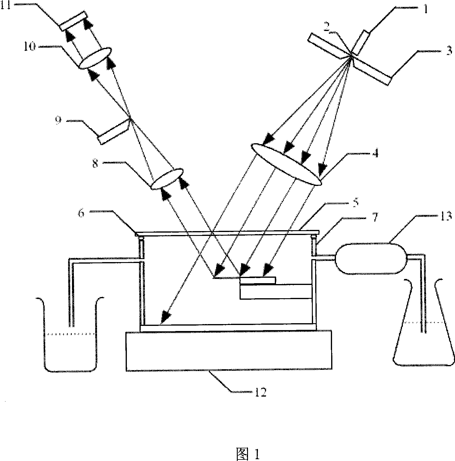
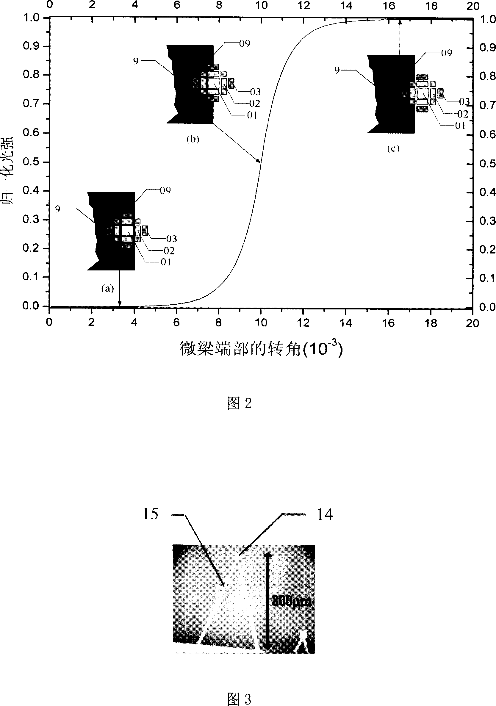
[0051] Referring to Fig. 1 and Fig. 3, the micro-cantilever beam 15 is placed in the reaction vessel 7 whose top is light-transmitting glass 5, and is sealed by the sealing ring 6, and the temperature change of the reaction vessel is controlled by the constant temperature system 12 contacted with the bottom of the vessel. The stability is ±0.01K, and the environment solution or the sample solution to be tested enters and exits the reaction vessel through the peristaltic pump 13 .
[0052] The optical monitoring device is composed of an optical lighting system, an optical filtering system and an optical imaging system. The optical lighting system is composed of a light source 1 , a light source filter hole 2 , a light barrier 3 and a light source lens 4 . The optical filtering system is composed of a Fourier transform lens 8 and an optical filtering unit 9 . The optical imaging system is composed of an imaging lens 10 and an optical receiver 11 .
[0053] The light source fil...
Embodiment 2
[0062] Compared with Embodiment 1, in this embodiment, the collimation of the illumination beam and the convergence of the reflected beam share a lens, which simplifies the mechanism. As shown in FIG. 3 , the lens 16 is commonly used as a light source lens and a Fourier transform lens. The light source filter hole 2 is placed on the front focal plane of the lens 16, and the beam line emitted by the light source filter hole 2 is collimated into a parallel beam through the lens 16 (this situation is as a light source lens), and this parallel beam is irradiated on the micro-cantilever beam 15 On the reflector 14 at the end, and be reflected by reflector 14, the diffracted light that returns from reflector 14 passes lens 16 again (this situation is as Fourier transform lens) and is converged on its rear focal plane, forms reflector 14 The optical diffraction spectrum, the subsequent process is consistent with embodiment 1.
Embodiment 3
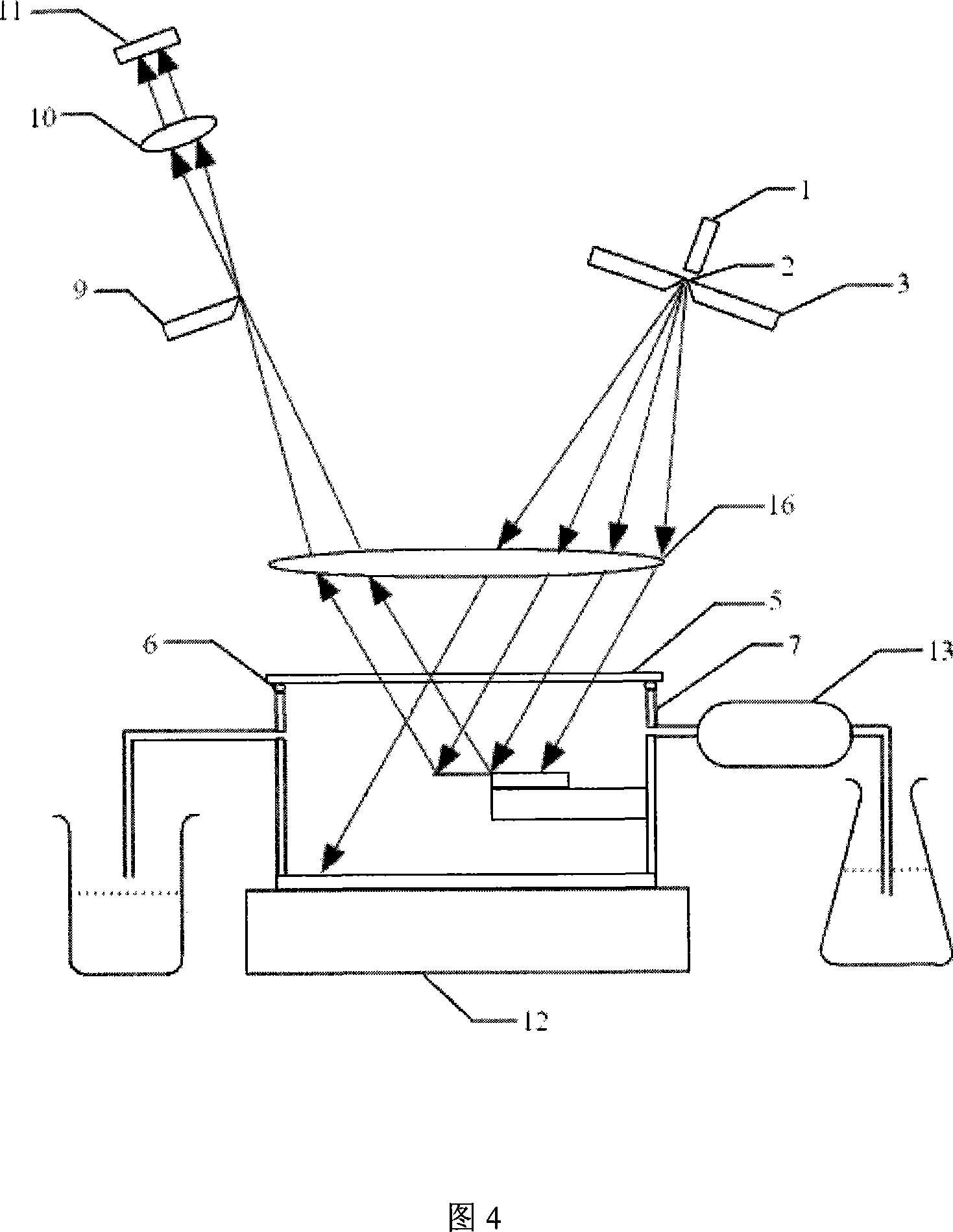
[0064] Referring to Fig. 4, this embodiment presents the structural form of the micro-cantilever beam optical filter "converging light illumination". The difference from Embodiment 1 is that the light emitted from the lighting system is not parallel light but converging light. Converging light can be achieved by placing the light source filter hole 2 at a position in front of the front focal plane of the light source lens 4 . The distance from the light source filter hole 2 to the front focus of the light source lens 4 directly affects the magnification of the optical measuring device. Since it is illuminated by converging light, the Fourier transform lens 8 of the optical filtering system can be omitted. The plane where the diffracted light converges is the optical spectrum plane of the micro-cantilever, and the optical filter unit 9 can be placed on this plane. The closer the light source filter hole 2 is to the front focus of the light source lens 4, the smaller the magnif...
PUM
| Property | Measurement | Unit |
|---|---|---|
| Length | aaaaa | aaaaa |
| Thickness | aaaaa | aaaaa |
Abstract
Description
Claims
Application Information
 - R&D
- Intellectual Property
- Life Sciences
- Materials
- Tech Scout
- Unparalleled Data Quality
- Higher Quality Content
- 60% Fewer Hallucinations
Browse by: Latest US Patents, China's latest patents, Technical Efficacy Thesaurus, Application Domain, Technology Topic, Popular Technical Reports.
© 2025 PatSnap. All rights reserved.Legal|Privacy policy|Modern Slavery Act Transparency Statement|Sitemap|About US| Contact US: help@patsnap.com


