Refrigerator
A technology for cold storage and controlled cooling, which is applied in the field of cold storage, and can solve problems such as frosting of coolers, long start-up time, and reduced heat exchange capacity of coolers, so as to achieve reliable stop and prevent a large amount of frosting
- Summary
- Abstract
- Description
- Claims
- Application Information
AI Technical Summary
Problems solved by technology
Method used
Image
Examples
no. 1 approach
[0040] A first embodiment of the present invention will be described with reference to FIGS. 1 to 10 .
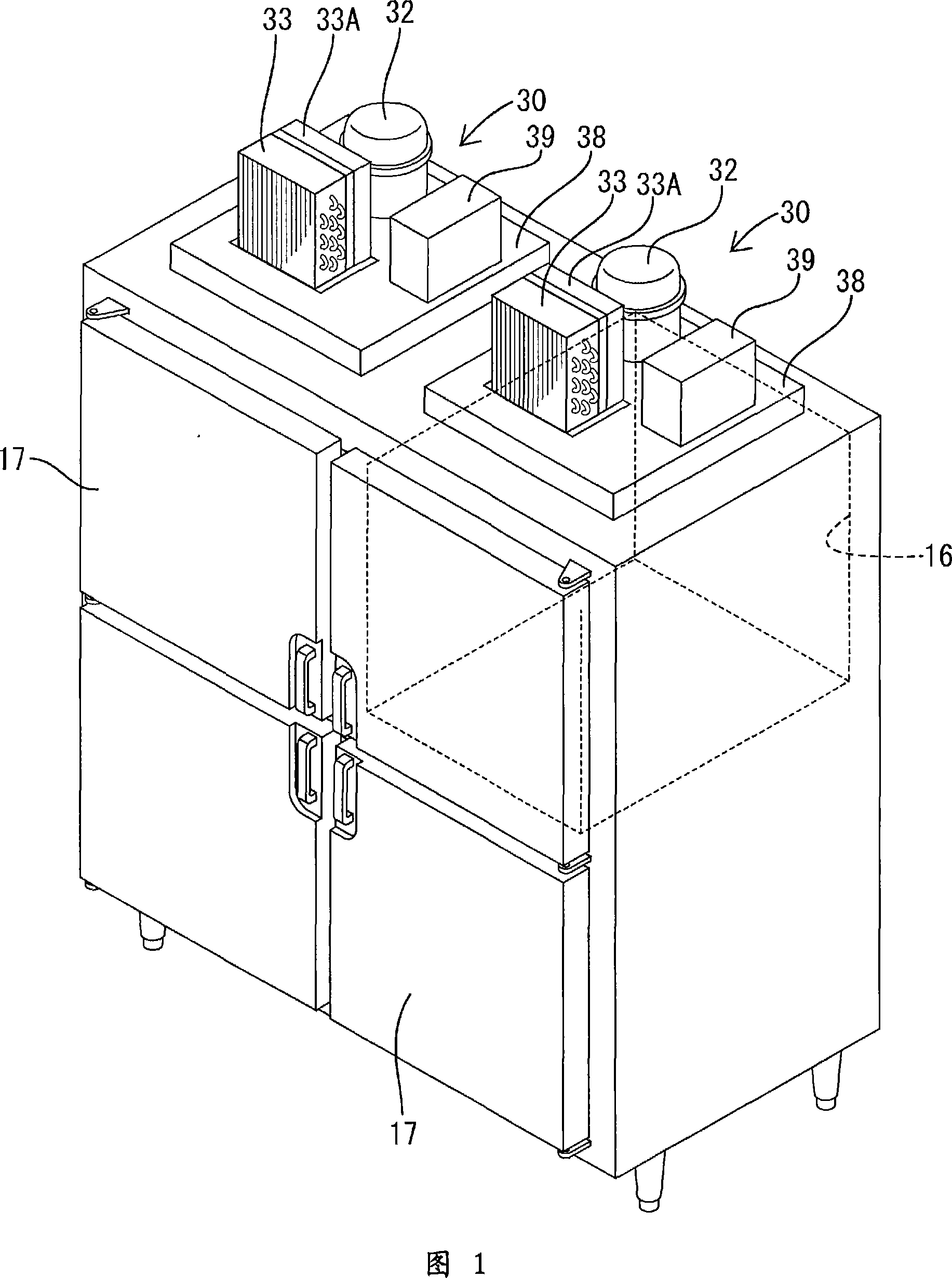
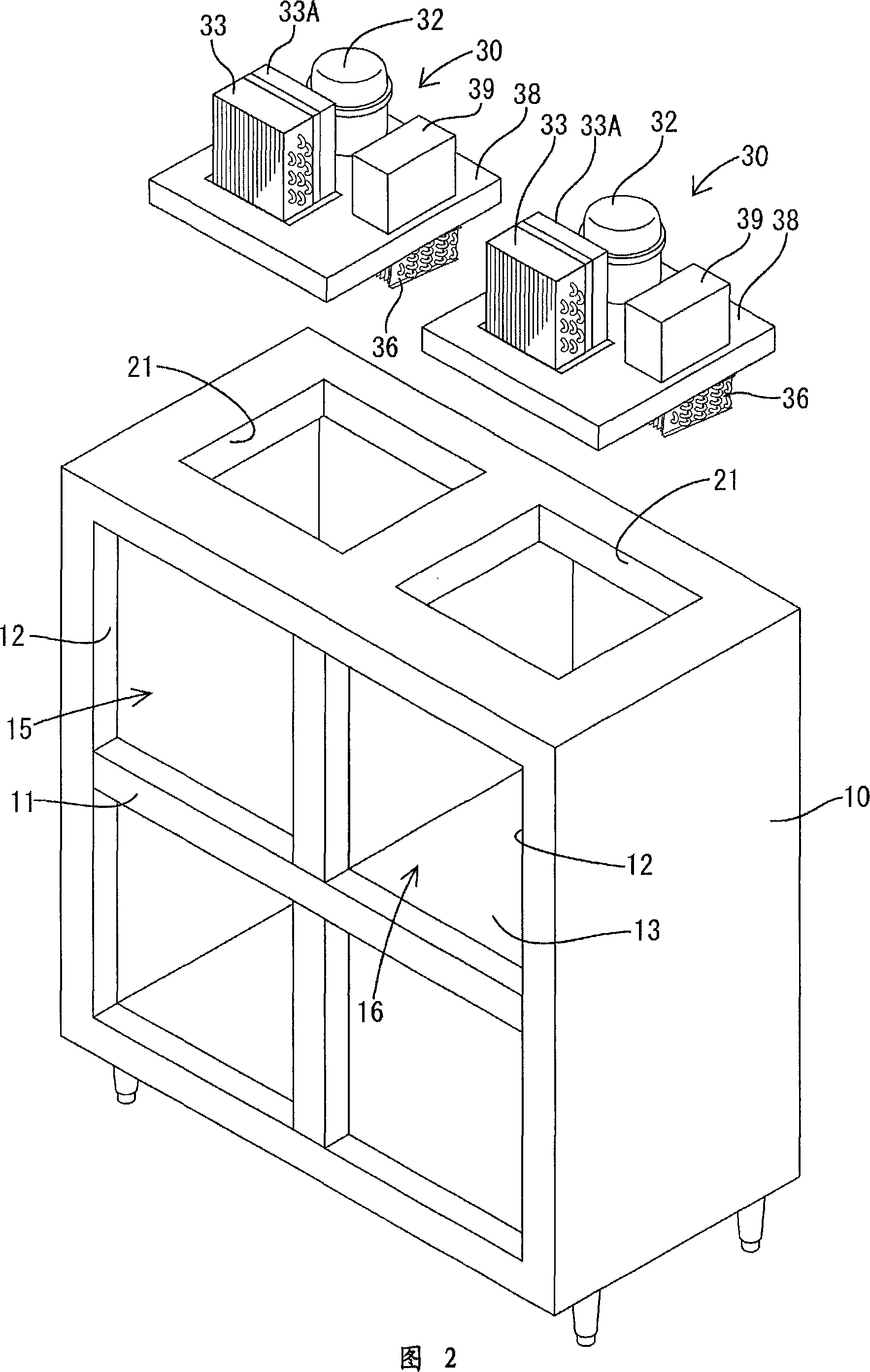
[0041] The refrigerator is a 4-door type. As shown in FIGS. 1 and 2, it has a main body 10 consisting of an insulated box with an open front. The front opening is divided by a cross-shaped partition frame 11 to form four entrances and exits 12. Viewed from the front, about 1 / 4 of the interior space corresponding to the entrance 12 on the upper right is divided by an insulating partition wall 13 to form a freezer 16 , and the remaining about 3 / 4 is used as a refrigerator 15 . A heat-insulating door 17 is attached to each entrance 12, and the door 17 can swing open and close.
[0042] On the upper surface of the main body 10, a machine room 20 is formed by erecting a board 19 (see FIG. 4 ) around the periphery. On the upper surface of the main body 10 which is the bottom surface of the machine compartment 20, rectangular openings 21 of the same size are formed corresponding ...
no. 2 approach
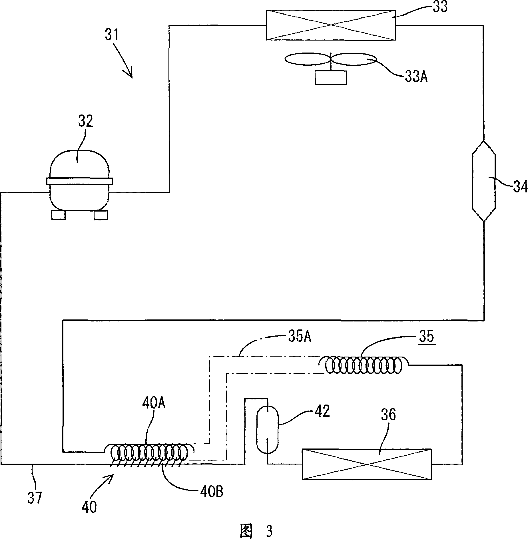
[0099] Next, a second embodiment of the present invention will be described with reference to FIG. 11 . The difference from the above-mentioned first embodiment lies in the configuration of software operating as the high temperature compensation control device, and the other configurations are the same as those of the first embodiment. Here, as shown in FIG. 11, when it is judged as “Yes” in step S15, when the cooling capacity of the cooling device 31 is increased, the measured cooling rate is compared with the target cooling rate in the same manner as when the cooling operation is controlled. The rotational speed of the inverter compressor 32 is determined based on the comparison result (step S17). That is, the larger the difference between the two, the faster the rotation speed. Here, the target cooling rate is set to three times (3xc) the target cooling rate during the controlled cooling operation, whereby a large cooling capacity is always exerted and the temperature in t...
no. 3 approach
[0101] 12 is a flow chart showing the operation of the controlled cooling operation and the high temperature compensation control device according to the third embodiment of the present invention. In the first embodiment, the cooling operation of the high temperature compensation control device ends when the internal temperature reaches the upper limit temperature TU (No in step S12), and returns to the controlled cooling operation. However, in the third embodiment In this case, when the temperature in the refrigerator reaches the lower limit temperature TL (NO in step S21), the cooling operation of the high temperature compensation control device is terminated. Others are the same as the above-mentioned first embodiment. In this case, as in the second embodiment, in the cooling operation of the high temperature compensation control device, the target cooling rate may be set higher (for example, three times) than the target cooling rate during the cooling control operation, th...
PUM
 Abstract
Description
Claims
Application Information
 - R&D
- Intellectual Property
- Life Sciences
- Materials
- Tech Scout
- Unparalleled Data Quality
- Higher Quality Content
- 60% Fewer Hallucinations
Browse by: Latest US Patents, China's latest patents, Technical Efficacy Thesaurus, Application Domain, Technology Topic, Popular Technical Reports.
© 2025 PatSnap. All rights reserved.Legal|Privacy policy|Modern Slavery Act Transparency Statement|Sitemap|About US| Contact US: help@patsnap.com


