Composite bar energy converter cleaning machine

A technology of transducers and composite rods, which is applied in the field of cleaning machines, can solve problems such as oil stains, dirt, and dust that are difficult to remove, reduce operation quality, and small bandwidth, and achieve good cleaning operation quality, wide operating frequency range, and structural simple effect

Inactive Publication Date: 2008-03-12
童晖
View PDF0 Cites 1 Cited by
  • Summary
  • Abstract
  • Description
  • Claims
  • Application Information

AI Technical Summary

Problems solved by technology

However, due to the defects in the structural design of the transducer, an existing electric and acoustic transducer can only have a fixed operating frequency, and the bandwidth is small, so the frequency cannot be changed. Oil stains, d

Method used


Image

  • Composite bar energy converter cleaning machine
  • Composite bar energy converter cleaning machine

Examples


Embodiment Construction

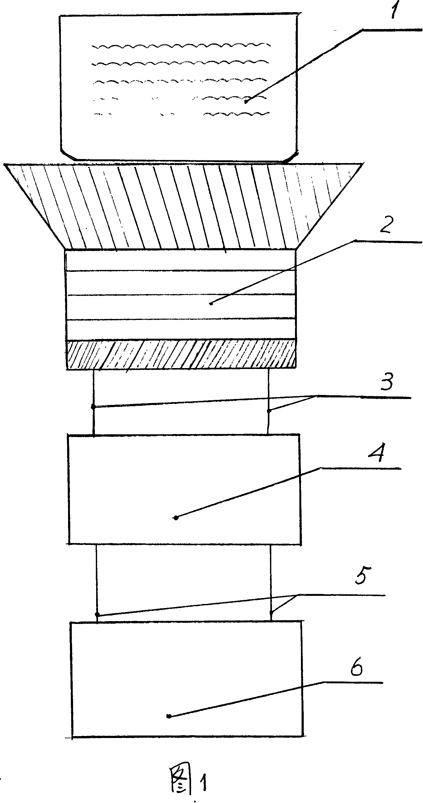
[0009] Embodiments of the invention will be described in detail below with reference to the accompanying drawings

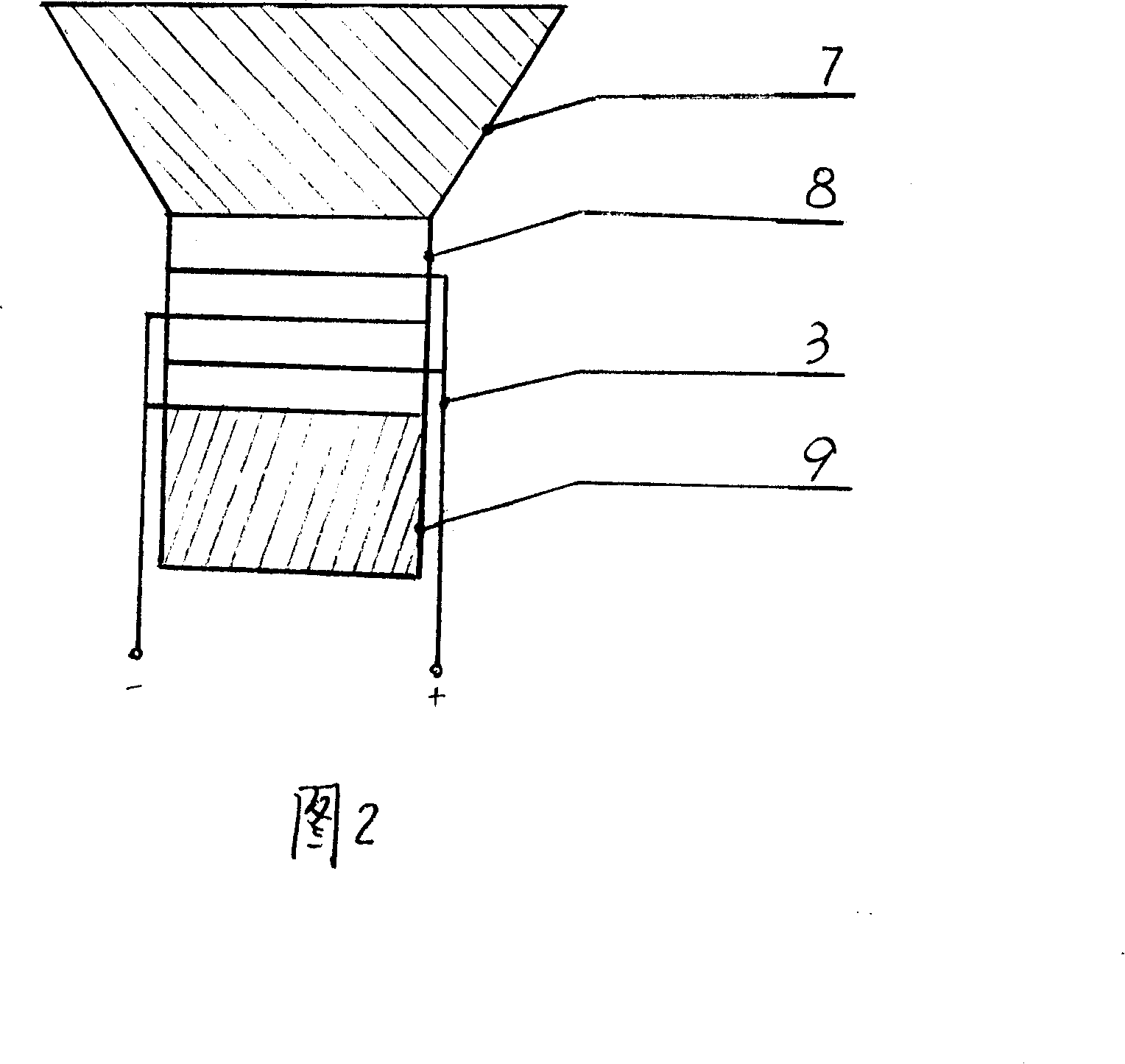
[0010] The composite rod transducer cleaning machine includes a liquid container 1, a power amplifier 4 and a signal source 6. The liquid container 1 is assembled on the upper part of the composite rod transducer 2, and the wire 3 and the wire 5 respectively connect the composite rod transducer 2 and the power amplifier 4. And the power amplifier 4 is connected with the signal source 6 . The composite rod transducer 2 is composed of a duralumin front cover 7, a piezoelectric ceramic stack 8 and a steel back cover 9. The hard aluminum front cover 7 and the steel back cover 9 are respectively assembled on the piezoelectric ceramics. On the upper and lower end surfaces of the stack 8 , the wires 3 are respectively connected to the positive and negative electrical contacts of the piezoelectric ceramic stack 8 .

[0011] When cleaning parts, put the cleaning liquid i...


PUM


Abstract

A compound bar transducer cleaning machine belongs to cleaning machinery. The compound bar transducer is provided with a vessel for holding liquid. The compound bar transducer and a power amplifier are connected by a conductor. The power amplifier and a signal source are connected by the conductor. The compound bar transducer consists of a duralumin front cover plate, a piezoelectric ceramics heap and a steel back cover plate. The conductor is connected with a positive electric contact and a negative electric contact of the piezoelectric ceramics heap. The utility model is able to turn electric energy into acoustic energy, thus, producing cavitation effect in water to finish clean-out operation. The utility model has advantages of simple structure, broad range of working frequency, wide application and good operation, which is especially suitable for washing the parts with gaps that are difficult to clean.

Description

technical field [0001] The invention belongs to a cleaning machine, and mainly relates to a cleaning machine for cleaning parts with a transducer converted from electrical energy into sound energy. Background technique [0002] At present, cleaning equipment that uses transducers that convert electrical energy into sound energy to clean parts with oil stains, dirt and dust has been applied in practical operations, and has brought positive effects to parts cleaning. However, due to the defects in the structural design of the transducer, the existing electric and acoustic transducer can only have a fixed operating frequency, and the frequency bandwidth is small, so the frequency cannot be changed. Oil stains, dirt and dust in the grooves and other depths are not easy to remove, which reduces the quality of work. Otherwise, multiple transducers in different frequency bands must be prepared, which increases the purchase cost and tedious cleaning operations. SUMMARY OF THE INVE...

Claims


Application Information

Patent Timeline
IPC IPC(8): B08B3/12B06B1/06
Inventor 童晖
Owner 童晖
Why Eureka
Try Eureka