Sample feeding system, anticollision device and anti-collision method

An anti-collision device and anti-collision technology, applied in the field of medical and chemical industry, can solve problems such as the collision of the sample adding system, and achieve the effects of ensuring the safety of people and equipment, easy detection process, and simple mechanical structure.

Active Publication Date: 2008-03-12
SHENZHEN MINDRAY BIO MEDICAL ELECTRONICS CO LTD
View PDF0 Cites 23 Cited by
  • Summary
  • Abstract
  • Description
  • Claims
  • Application Information

AI Technical Summary

Problems solved by technology

[0006] The main purpose of the present invention is to solve the above-mentioned problem of preventing the collision of the sample feeding system, to provide a kind of anti-collision device and method for the sample feeding system, and to effectively prevent the sample feeding system from colliding with other samples during the movement process with a low-cost design. objects collide

Method used


Image

  • Sample feeding system, anticollision device and anti-collision method
  • Sample feeding system, anticollision device and anti-collision method

Examples


Embodiment 1

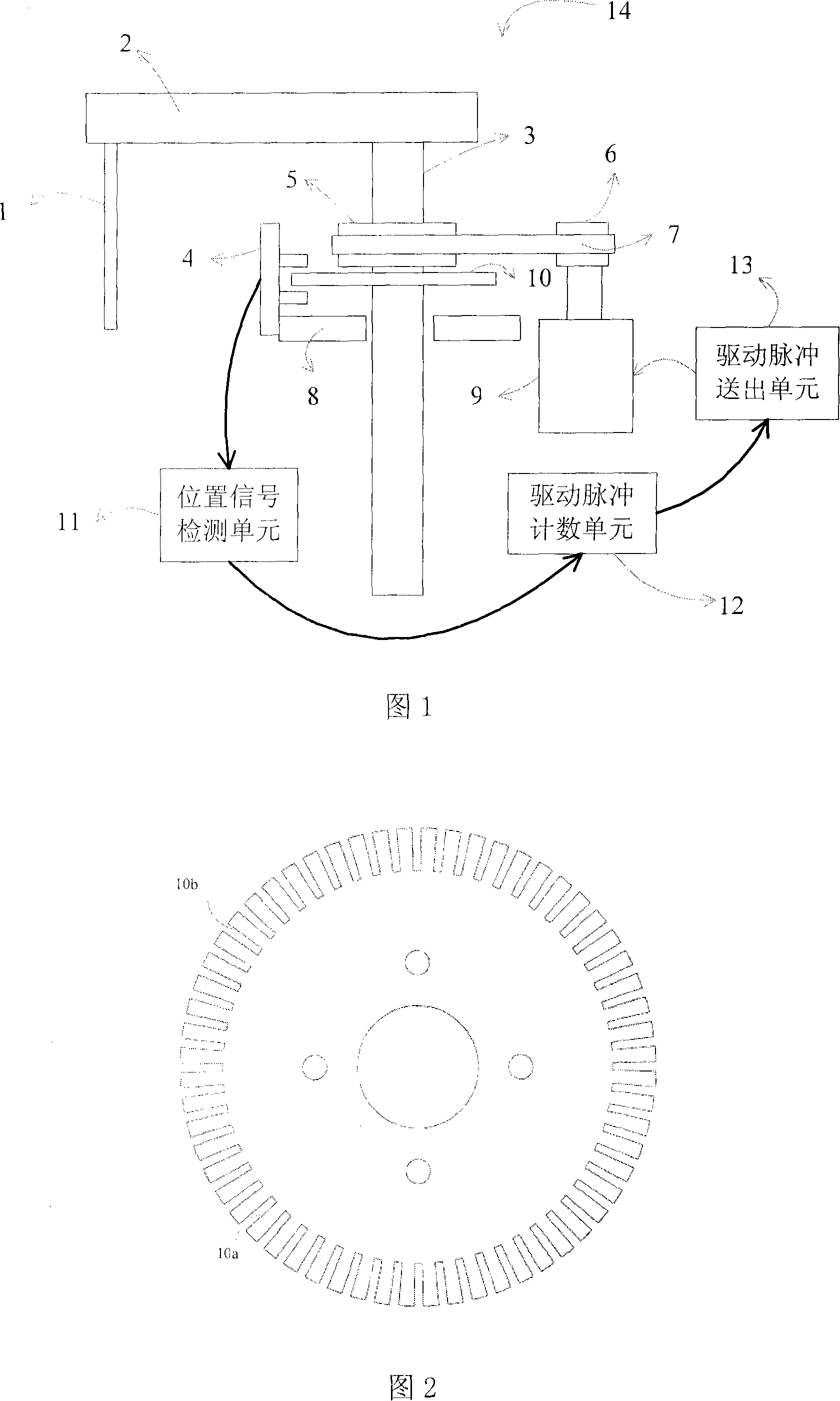
[0037] Embodiment 1. This embodiment is an application of the present invention in a rotary sample feeding system. The moving mechanism is a rotating mechanism, including a rotating shaft. The overall structure of the sample feeding system 14 is shown in Figure 1, the driving motor 9 is connected to the small pulley 6 and drives it to rotate, the small pulley 6 is connected to the large pulley 5 through the timing belt 7, and the rotational motion is transmitted to the large pulley 5 , the large pulley 5 drives the rotating shaft 3 and the code disc 10 to move synchronously. The probe 1 is connected with the rocker 2, and the rocker 2 connected thereto is driven by the rotating shaft 3 to rotate the probe 1 to a designated position. The code disc 10 is a circular disc, and the edge of the code disc 10 is equidistantly provided with light-transmitting gaps 10a, and the light-transmitting gaps 10a can be bar-shaped or tooth-shaped apertures, as shown in Figure 2, and can also be...

Embodiment 2

[0046] Embodiment 2, the present invention can also be applied in a linear motion sample adding system, the moving mechanism is a linear motion mechanism, the preferred solution is that the optical coupler is fixed on the moving mechanism and moves with the moving mechanism, the code disc is a rectangular disc, and is The accessories fixed on the moving track of the moving mechanism do not move with the moving mechanism, and one edge of the code disc is parallel to the moving track of the moving mechanism, so that the code disc penetrates the light gap into the detection position of the optocoupler. The position signal detection unit, the driving pulse counting unit and the driving pulse sending unit can be the same as those in the first embodiment, and have the same anti-collision function as the first embodiment.

[0047] It should be noted that the above-mentioned code wheel with a light-transmitting gap can be replaced by a mark wheel with uniformly distributed micromirrors...


PUM


Abstract

The present invention discloses a sampling system anti-collision device and an anti-collision method. The sampling system comprises a moving mechanism, a motor and so on. The anti-collision device comprises a code wheel, an optical coupling, a position signal detecting unit, a drive pulse counting unit and a drive pulse delivery unit. Wherein, the code wheel or the optical coupling is connected with the moving mechanism. The code wheel is provided with uniformly-spaced transparent slits. The optical coupling detects the transparent slit on the code wheel while moving relatively and outputs a detecting signal with periodical level variation. In addition, the position signal detecting unit determines whether a position signal is output to the drive pulse counting unit. The drive pulse counting unit judges whether the sampling system undergoes collision according to the position signal. Moreover, the present invention discloses a sampling system comprising the anti-collision device. The present invention can effectively detect collision state of the sampling system, make immediate response, stop sampling system operation, ensure personal safety and prevent instrument damages.

Description

【Technical field】 [0001] The invention relates to a sample adding system in the medical and chemical industry field, and also relates to an anti-collision device in the sample adding system and an anti-collision method thereof. 【Background technique】 [0002] In the field of medical chemical industry, it is often necessary to use a sampling system. Now the commonly used sampling system is a sampling system that can automatically sample and add samples. During the movement (such as rotation or linear motion), the sampling system It may collide with the human body or other objects that are changing samples or reagents, or the sampling system may collide with other equipment due to control errors, resulting in damage to the sampling system and errors in test results. What is more serious is that it is very likely Can cause harm to the human body. In order to ensure the safety of the person and the equipment, it is necessary to make a judgment on the collision that occurs durin...

Claims


Application Information

Patent Timeline
Patent Type & Authority Applications(China)
IPC IPC(8): G01N35/10G01N35/00
Inventor 翁彦雯胡建坤朱星才
Owner SHENZHEN MINDRAY BIO MEDICAL ELECTRONICS CO LTD
Why Eureka
Try Eureka