Design of ultra-applanation fuel battery engines air conveying device

An air conveying device and fuel cell technology, which is applied to fuel cell components, fuel cells, fuel cell additives, etc., can solve the problems of limited installation space, large volume, and inability to install, and achieve space saving and small volume Effect

Inactive Publication Date: 2008-03-12
SHANGHAI SHENLI TECH CO LTD
View PDF2 Cites 0 Cited by
  • Summary
  • Abstract
  • Description
  • Claims
  • Application Information

AI Technical Summary

Problems solved by technology

However, the height of this air delivery device is still too high and the volume is too large to be installed in a small space, especially the air delivery device for a fuel cell engine is used in a bus or a car, and the installation space is even more limited

Method used


Image

  • Design of ultra-applanation fuel battery engines air conveying device
  • Design of ultra-applanation fuel battery engines air conveying device
  • Design of ultra-applanation fuel battery engines air conveying device

Examples


Embodiment 1

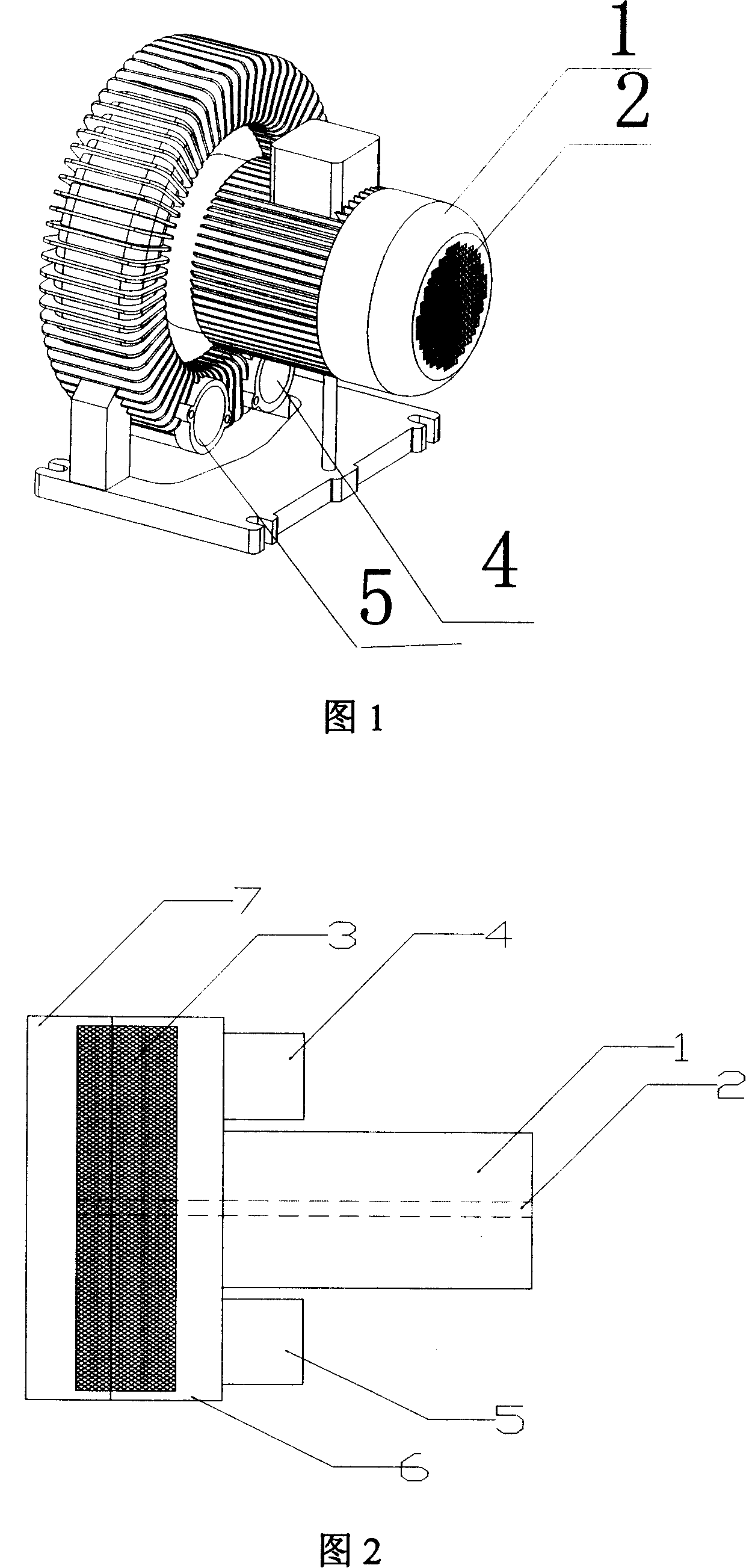
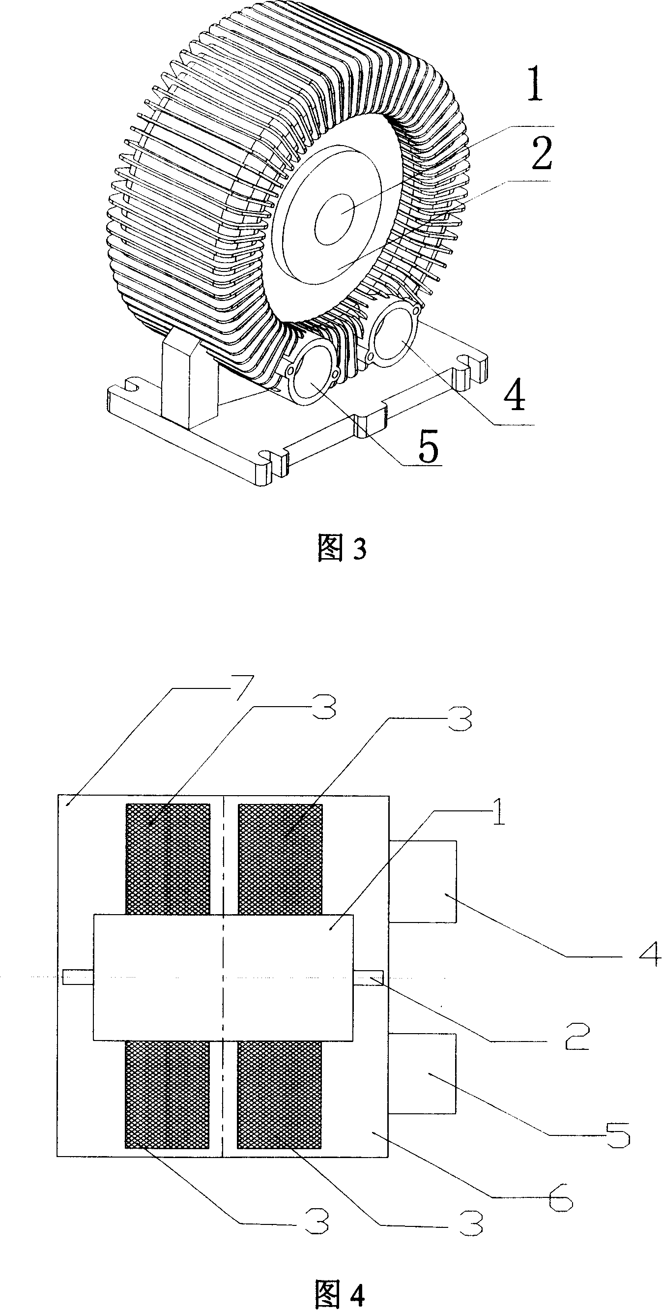
[0029] As shown in Figures 3 and 4, the design of an ultra-flat fuel cell engine air delivery device includes the outer rotor 1 of the motor, the central stator 2 of the motor, the impeller 3 of the fan, the air suction port 4, the air outlet 5, and the upper part of the fan. The drum 6, the lower drum 7 of the fan, the central stator 2 of the motor is fixed on the upper and lower drums 6, 7 of the fan, and the outer rotor 1 of the motor is directly provided with an impeller 3, so that the motor and the fan drum are integrated, The height of the whole air conveying device is the sum of the heights of the upper and lower drum discs of the fan, and the air suction port 4 and the air outlet port 5 are arranged on the drum disc.

[0030] The impeller can be provided with 1 to 4 as required, and this embodiment is provided with 2; the material of the impeller includes metal and plastic, and this embodiment uses engineering plastics, such as polytetrafluoroethylene plastic; the sucti...

Embodiment 2

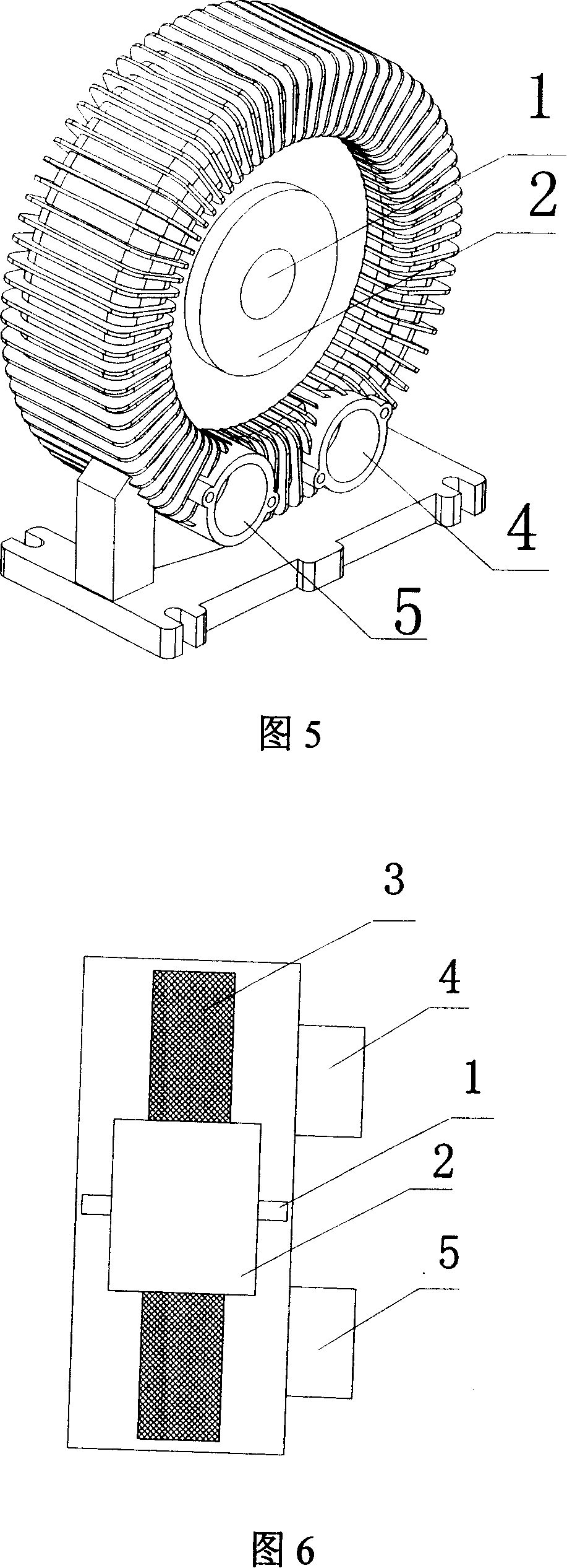
[0032] As shown in Figures 5 and 6, the design of an ultra-flat fuel cell engine air delivery device includes the outer rotor 1 of the motor, the central stator 2 of the motor, the impeller 3 of the fan, the air suction port 4, the air outlet 5, and the upper part of the fan. The drum 6, the lower drum 7 of the fan, the central stator 2 of the motor is fixed on the upper and lower drums 6, 7 of the fan, and the outer rotor 1 of the motor is directly provided with an impeller 3, so that the motor and the fan drum are integrated, The height of the whole air conveying device is the sum of the heights of the upper and lower drum discs of the fan, and the air suction port 4 and the air outlet port 5 are arranged on the drum disc.

[0033] The impeller can be provided with 1 to 4 as required, and one is provided in this embodiment; the material of the impeller includes metal and plastic, and metal material is used in this embodiment; The same side or the different side of the disc, ...


PUM


Abstract

The invention relates to a design for air delivery device of an ultra-flat fuel cell engine, which comprises an electromotor, an impeller, a fan up-or-down drum, an inlet scoop and an outlet scoop. The central stator of electromotor is positioned on the fan up-or-down drum and the impeller is directly settled on the outer stator of the electromotor, which integrates the electromotor and the fan drum. The height of the whole air delivery device is the sum of fan up-or-down drum. The inlet scoop and the outlet scoop are equipped on the drum. Compared with the prior art, the design structure of the electromotor and drum integration is characterized in small volume and saving space. Besides, the performance of feeding wind is equal to the height of regular fan, and the impeller is directly positioned on the electromotor for self-heat-radiation when transferring wind.

Description

technical field [0001] The invention relates to a fuel cell, in particular to the design of an air conveying device for an ultra-flat fuel cell engine. Background technique [0002] An electrochemical fuel cell is a device that converts hydrogen and oxidants into electrical energy and reaction products. The internal core component of the device is the membrane electrode (Membrane Electrode Assembly, referred to as MEA). The membrane electrode (MEA) is composed of a proton exchange membrane and two porous conductive materials, such as carbon paper, sandwiched between the two sides of the membrane. On the two boundary surfaces of the membrane and the carbon paper, there are even and finely dispersed catalysts for initiating electrochemical reactions, such as metal platinum catalysts. Conductive objects can be used on both sides of the membrane electrode to draw the electrons generated during the electrochemical reaction through an external circuit to form a current loop. [...

Claims


Application Information

Patent Timeline
Patent Type & Authority Applications(China)
IPC IPC(8): H01M8/00H01M8/04H01M8/06H01M8/02H01M8/04111
CPCY02E60/50
Inventor 章波胡里清
Owner SHANGHAI SHENLI TECH CO LTD
Why Eureka
Try Eureka