Laser automatic optical power control circuit

A technology for optical power control and lasers, which is applied in the field of lasers and can solve the problems of high adjustment accuracy and waste

Active Publication Date: 2008-03-12
ZTE CORP
View PDF0 Cites 6 Cited by
  • Summary
  • Abstract
  • Description
  • Claims
  • Application Information

AI Technical Summary

Problems solved by technology

[0017] In the prior art, the trans-resistance Rtz is generally realized by a potentiometer. When a digital potentiometer is used, the adjustment accuracy of the output power will change with the resistance value of the potentiometer. When the resistance value of Rtz is large, ΔPout is small, and When the resistance value of Rtz is small, ΔPout will be large. If the user requires high adjustment accuracy of the output power, the number of digits of the potentiometer needs to be increased to make up for the lack of adjustment accuracy at one end of the potentiometer, while at the other end of the potentiometer , the adjustment accuracy is too high to cause waste
[0018] With the advancement of laser technology, high-performance lasers continue to emerge, and the control accuracy of each parameter of the laser is also increasing. Among them, the output power of the laser is an important parameter, and it has higher control accuracy requirements in many applications. , this requirement cannot be well met using the aforementioned conventional power control

Method used


Image

  • Laser automatic optical power control circuit
  • Laser automatic optical power control circuit
  • Laser automatic optical power control circuit

Examples


Embodiment Construction

[0035] Specific embodiments of the present invention will be described in detail below in conjunction with the accompanying drawings.

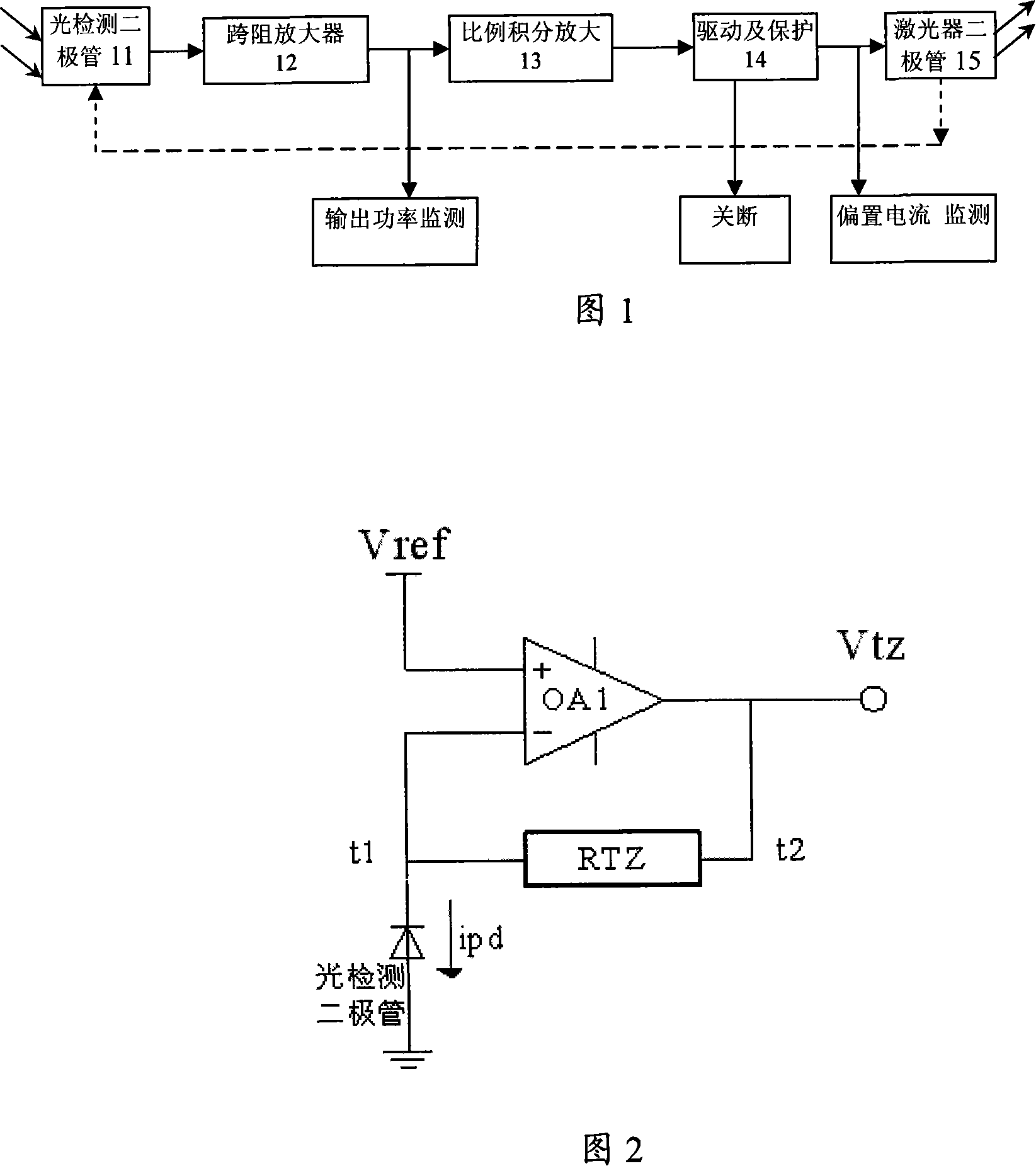
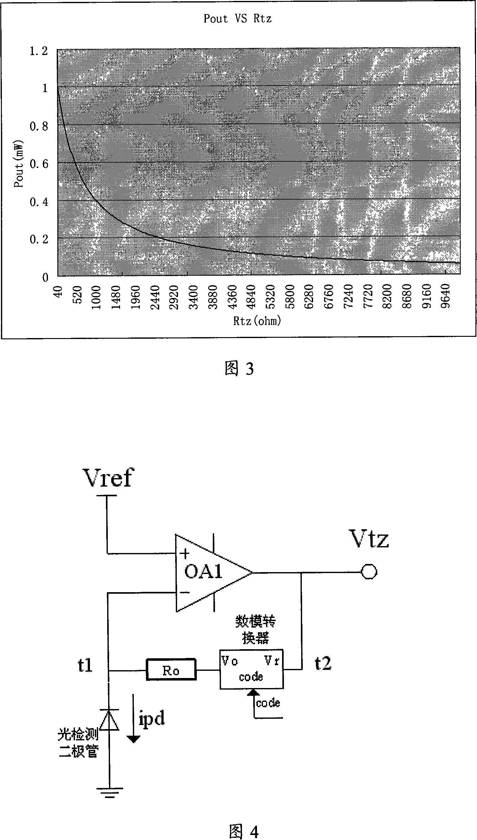
[0036] As shown in Figure 4, in the circuit of the present invention, traditional transimpedance amplifier 12 uses DAC to add fixed resistance R 0 Instead of the digital potential Rtz to realize the adjustment function, it can be obtained from Figure 4 that the photo-generated current Ipd on the PIN tube 11 is determined by the output voltage Vo of the DAC and the fixed resistance R 0 Determined by the resistance value, its relationship can be expressed as:

[0037] Ipd=(Vo-Vref) / R 0 (6)

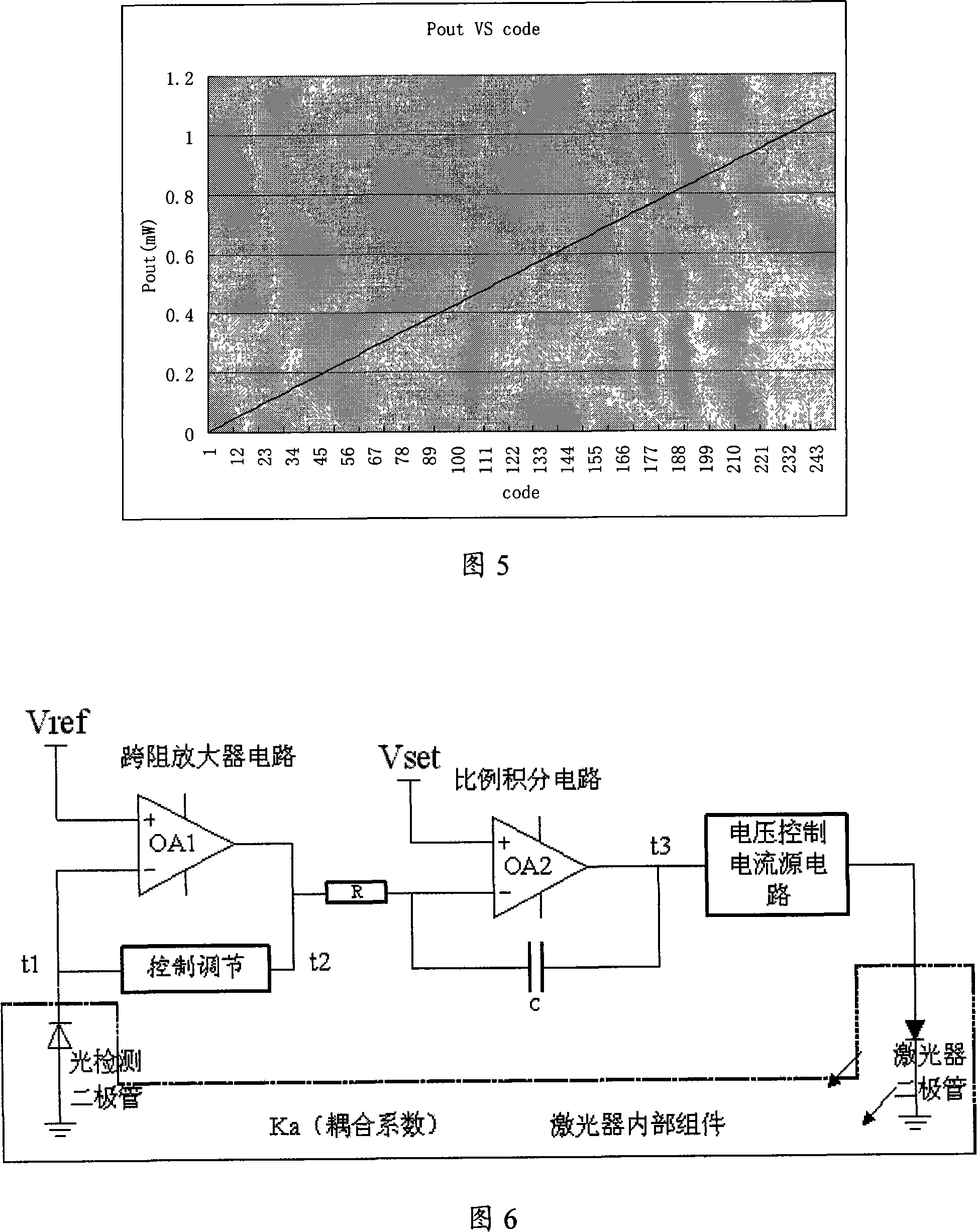
[0038] DAC output voltage Vo=code*Vr / 2 n , where code is the value written to the DAC, and the value range is 0 to 2 n -1, n is the number of digits of the DAC, Vr is the input reference voltage of the DAC, and Vtz is sent to the DAC as a reference voltage in the present invention. When the APC circuit works stably, Vtz will be equal to Vset. At thi...


PUM


Abstract

The invention relates to the field of automatic optical power control of laser, which discloses an automatic optical power control system of laser, comprising a detecting diode for optical power in trailing direction, TIA, proportional integrated circuit, power driver, protective circuit and the laser diode. The said TIA is composed of an operational amplifier, a digital-analog converter and a fixed resistance; The reference input Vr of the said digital-analog converter is connected with the output terminal of the operational amplifier whose output voltage is linked with the fixed resistance; The other end of the fixed resistance is connected with the reverse input terminal of the operational amplifier. Based on the existing topological structure of the circuit, the invention realizes the linearization and high precision adjustment of the optical power control circuit by manipulating the digital-analog converter.

Description

technical field [0001] The invention relates to the technical field of lasers, in particular to the field of automatic optical power control of lasers, and in particular to a circuit for realizing automatic optical power control of lasers. Background technique [0002] Laser optical power control uses the back-facing light detector in the laser component to convert the back-facing light output power of the laser into photocurrent. After the photocurrent is amplified, it feeds back the bias current of the laser to make the output back-facing optical power of the laser a fixed value. So as to achieve the purpose of stabilizing the optical power of the laser. [0003] As shown in Figure 1 is the working principle diagram of APC (automatic optical power control circuit). Impedance amplifier) ​​12, proportional integral circuit 13, power drive and protection circuit 14 and LD (laser diode) 15, the photocurrent output through the backlight detection power detection diode 11 is co...

Claims


Application Information

Patent Timeline
Patent Type & Authority Applications(China)
IPC IPC(8): H01S5/0683H01S3/13
Inventor 张赟崔平
Owner ZTE CORP
Why Eureka
Try Eureka