Optical power display and regulation device

A technology for adjusting devices and optical power, applied in electromagnetic wave transmission systems, electrical components, transmission systems, etc., can solve problems such as business interruption, and achieve the effect of overcoming the limitations of instrumentation, realizing real-time monitoring and management, and simple human-computer interaction

Inactive Publication Date: 2008-03-12
ZTE CORP
View PDF0 Cites 8 Cited by
  • Summary
  • Abstract
  • Description
  • Claims
  • Application Information

AI Technical Summary

Problems solved by technology

[0007] Testing the optical power and adding a fixed attenuator often requires cutting off the optical path connection resulting in service interruption

Method used


Image

  • Optical power display and regulation device
  • Optical power display and regulation device

Examples


Embodiment Construction

[0033] The specific implementation manners of the present invention will be further described in detail below in conjunction with the accompanying drawings.

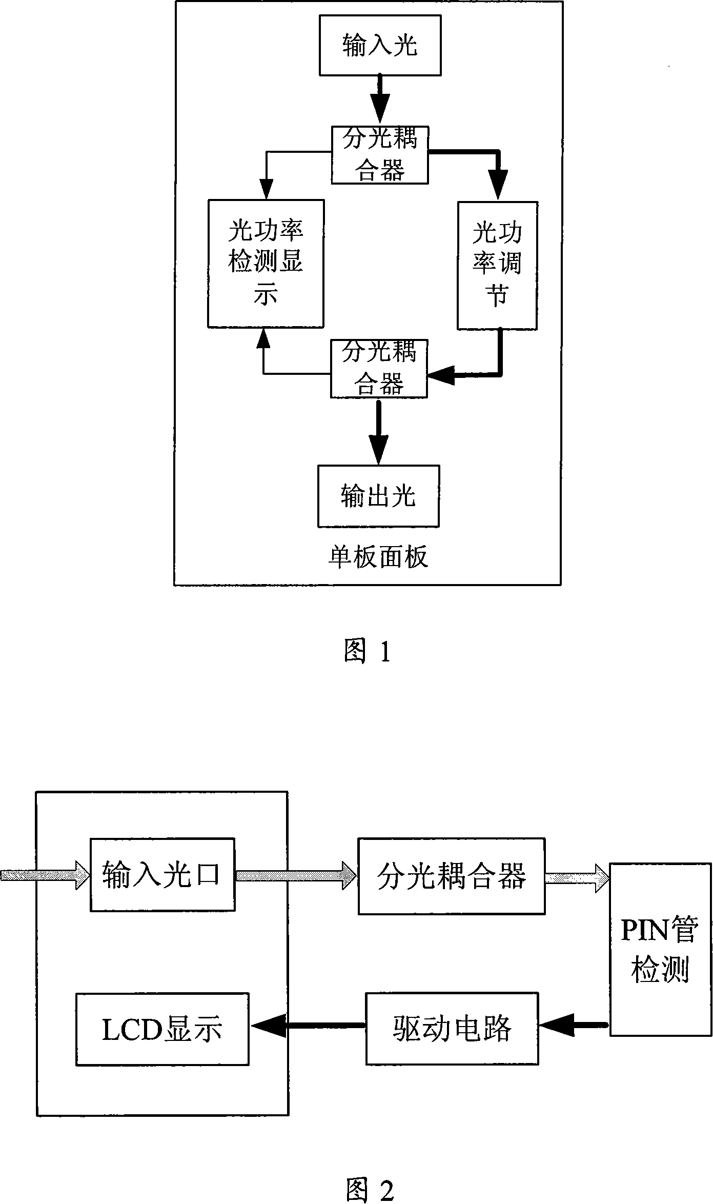
[0034] Accompanying drawing 1 has introduced the schematic diagram of the device for realizing optical power display and adjustment.

[0035] Compared with the traditional optical power detection, display and adjustment methods, the present invention specifically includes: an optical input port, an optical coupler, an optical power detection unit, an optical power display unit, an optical power adjustment unit and an optical output port, and an optical path is established between them Connection, the optical power detection unit, optical power display unit and optical power adjustment unit are added on the single board panel, the single board panel is the optical input port, optical output port, optical coupler, optical power detection unit, optical power display unit and optical power Regulatory cell carrier.

[0036] ...


PUM


Abstract

The utility model relates to an optical transmission device for the field of communication, more particularly discloses a luminous power display and regulating unit, which comprises an optical input port, an optical coupler, a luminous power examination unit, a luminous power display unit, a luminous power control unit and a light yield port which are connected via the light path. So, the luminous power examination unit, the luminous power display unit and the luminous power control unit are added on the single board. Therefore, as compared with the existing technology, the utility model has the advantages that the Instruments and meters' limits are overcome; the pigtail used for measuring is saved; the real-time monitoring and control can be realized for the luminous power performance even though the network administration surroundings are unavailable or do not work, so as to achieve the simple man machine interaction; acting as both the monitor and the actuator in the power control system, so as to realize the close regulation of the luminous power; the power detection can be embedded to the light path. Thus, the luminous power value can be monitored while the operation is undisrupted.

Description

technical field [0001] The invention relates to optical transmission equipment in the communication field, in particular to an optical power display and adjustment device, which is beneficial to realizing intelligent management and utilization of resources in an optical transmission network. Background technique [0002] In the DWDM (Dense Wavelength Division Multiplexing) optical transmission network, the optical power of the DWDM system will fluctuate after long-distance transmission, which will seriously affect the performance of the system, cause the decrease of the optical signal-to-noise ratio, and increase the bit error rate, seriously will damage the device. In order to avoid the above situation, it is necessary to adopt a complete optical power management technology when building a dense wavelength division multiplexing system to adjust and configure the optical power in the system so that the power of the main optical channel can be balanced. Therefore, how to quic...

Claims


Application Information

Patent Timeline
Patent Type & Authority Applications(China)
IPC IPC(8): H04J14/02H04B10/08H04B10/12H04B10/071H04B10/079
Inventor 王巍鑫
Owner ZTE CORP
Why Eureka
Try Eureka