Water-controlled valve tube, water-controlled head and micro-irrigator

A water control valve and water head technology, which can be used in automatic watering devices, botanical equipment and methods, gardening, etc., and can solve problems such as hindering widespread use and high capital investment.

Inactive Publication Date: 2010-07-28
쥬쮠
View PDF5 Cites 0 Cited by
  • Summary
  • Abstract
  • Description
  • Claims
  • Application Information

AI Technical Summary

Problems solved by technology

If deep water treatment is done in advance, it means that the normal operation of the system requires high capital investment, which will hinder the widespread use of this technology in agriculture and forestry

Method used


Image

  • Water-controlled valve tube, water-controlled head and micro-irrigator

Examples


Embodiment 1

[0040]As shown in Figures 1 and 2, the present invention provides a water control valve tube 1, which includes an outer shell 12 and an inner core 11 disposed in the outer shell 12, the outer shell 12 is provided with a water inlet 121 and a water outlet 122, The inner core 11 is composed of a bundle of hydrophilic threads, the hydrophilic threads at least extend from the water inlet end 121 to the water outlet end 122, and the average gap between the hydrophilic threads in at least part of the inner core 11 gradually decreases along the water flow direction.

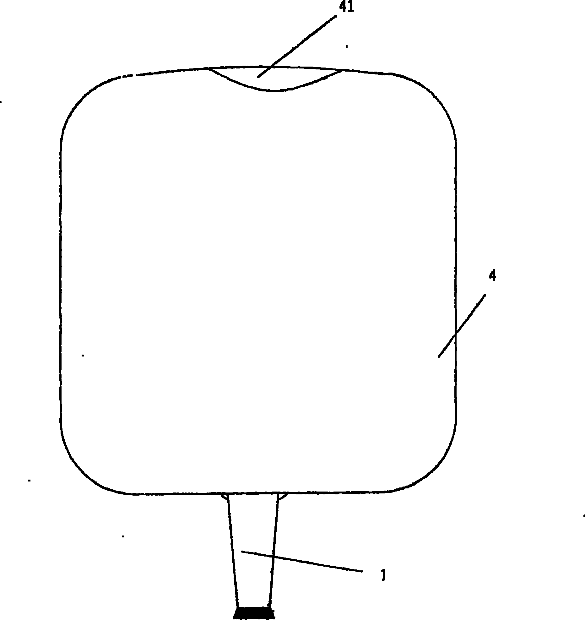
[0041] The water control valve tube of the present invention can be connected to a water storage container to form a micro-irrigator. In this way, it is only necessary to bury the micro-irrigator with the water control valve pipe into the soil without laying water supply pipes to evenly send water to the plant root system, and then replace the water storage container regularly or add water to the water storage container ...

Embodiment 2

[0065] The principle and structure of this embodiment and embodiment 1 are basically the same, the difference is that as shown in Figure 6, the shell 12 of the water control valve tube 1 can be a cylindrical structure, and the hydrophilic line extends out of the water inlet end 121 (Figure 6 not shown), the average gap between the hydrophilic lines outside the water inlet 121 gradually becomes smaller along the water flow direction. In this embodiment, due to the hydrophilic line extending out of the water inlet end 121 , the average gap along the direction of water flow gradually becomes smaller, therefore, the same effect as in the embodiment can be achieved when water flows through.

Embodiment 3

[0067] As shown in Figure 7, the present invention also provides a water control head, including a filter cavity 2, the filter cavity 2 is provided with a water inlet 21 and at least one water outlet 22, the diameter of the water inlet 21 is larger than the diameter of the water outlet 22 The water inlet 21 is provided with a filter element 23, the water outlet 22 is connected with at least one aforementioned water control valve tube 1, the water control valve tube 1 includes a shell 12 and an inner core 11 penetrating through the shell 12, The shell 12 is provided with a water inlet 121 and a water outlet 122. The inner core 11 is composed of a bundle of hydrophilic threads. The hydrophilic threads at least extend from the water inlet 121 to the water outlet 122. At least part of the inner core 11 The average gap between hydrophilic lines gradually decreases along the direction of water flow.

[0068] In practical application, in order to prevent the water quality from causin...


PUM


Abstract

The invention is provided with a water controlling valve pipe, water controlling head and microirrigator. The water controlling valve pipe includes a housing and a core positioned within the housing, the housing is provided with a water inlet and water outlet, the core is formed of a bundle of hydrophilic string, the hydrophilic string extend to the water outlet from the water inlet at any rate, the average space among at least part of hydrophilic string in the core becomes small little by little along the direction of water flow. The impurities is spaced and fixed on the different cross sections according to its size and the angle in the water, the smaller impurities can flow through the space, thus which couldn't provide ''unwanted block'' in the pipe.

Description

technical field [0001] The invention relates to a micro-irrigation device, in particular to a water control valve pipe, a water control head and a micro-irrigator. Background technique [0002] The most water-saving agricultural irrigation today is micro-irrigation, such as drip irrigation and infiltration irrigation, whose water supply rate can be as low as 3-5 liters of water per hour. However, through a large number of experiments, it has been found that the daily water requirement of many plant seedlings is only a few hundred milliliters or even tens of milliliters. Obviously, drip irrigation and infiltration irrigation also have amazing waste. The reason is that the water outlet aperture of the drip osmosis head is generally above 1-0.5 mm. In this case, the capillary tube plays a very limited role in controlling the water flow, so the water outlet speed of the drip osmosis head is still too fast. [0003] In order to solve this problem, the applicant invented a quanti...

Claims


Application Information

Patent Timeline
IPC IPC(8): A01G27/04
CPCA01G27/006A01G27/008
Inventor 诸钧
Owner 쥬쮠
Why Eureka
Try Eureka