High-pressure water sand-spraying deflashing machine

A technology for removing flash and high-pressure water, applied in abrasives, spray guns, sedimentation separation, etc., can solve the problems of poor controllability, unreliable and stable feeding of strips, etc., and achieve the effect of stable and orderly transportation

Inactive Publication Date: 2008-03-19
GRAND TECH SHENZHEN
View PDF0 Cites 13 Cited by
  • Summary
  • Abstract
  • Description
  • Claims
  • Application Information

AI Technical Summary

Problems solved by technology

However, there are still problems of poor controllability of loading and unloadi

Method used


Image

  • High-pressure water sand-spraying deflashing machine
  • High-pressure water sand-spraying deflashing machine
  • High-pressure water sand-spraying deflashing machine

Examples


Embodiment Construction

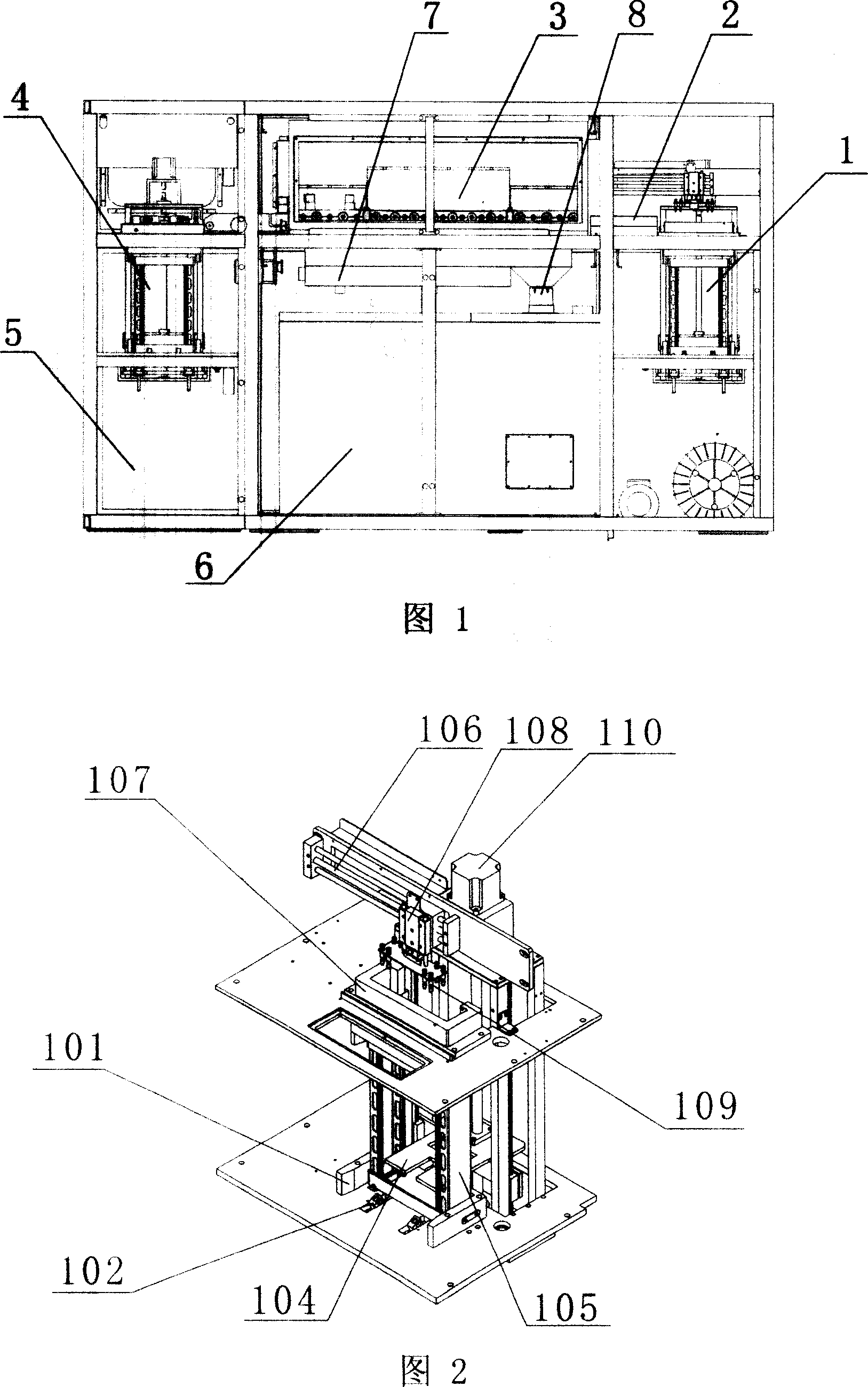
[0025] The present invention is a kind of high-pressure water sand blasting machine for removing overflow, as shown in Figure 1, it includes a feeding device 1, a material pushing device 2, a transmission and conveying mechanism, a material removing system 3, a feeding device 4 and an automatic control system. system, the de-overflow system includes a sand-collecting type water-sand separation box 6, several water-sand spray heads, some clear water spray heads, an air-drying device and a high-pressure water pump 5, and is characterized in that the feeding device 1 is The IC material strips are sent to the pusher into the warehouse by means of a transmission mechanism; the transmission and conveying mechanism drives the material strips forward through the upper and lower rows of roller shafts; the unloading device 4 uses the weight of the material strips to drop to the corresponding position through the blanking mechanism. According to the sequence of loading IC strips into the ...


PUM


Abstract

The invention relates to a cleaning equipment for a IC molding strip flash, to be more precise, relates to a flash machine with a IC strip high pressure water sand-blast. The invention comprises a charging device, a material pushing and storage device, a transmission part, a spewing system, a baiting device and an automatic control system. The spewing system comprises a sand-collection sand-and-water separation bin, a plurality of sand-and-water spray heads, a plurality of water spray heads, a dried device and a high-pressure pump. The invention is characterized in that the charging device pushes the IC strip into the pushing and storage device through a vacuum grasp manner. The transmission part drives the strips to progress through a drive shaft in an upper and a lower rows. Through a blanking part, the baiting device drives the strip to fall to the location with its own body weight. The invention has the characteristics of easy control of charging and baiting, good processing quality and high efficiency.

Description

technical field [0001] The invention relates to a cleaning device for material strip overflow after IC mold sealing, and more precisely relates to an IC material strip high-pressure water sandblasting machine for removing overflow. Background technique [0002] In the post-process of semiconductor IC module manufacturing, laser deflashing equipment is currently used more frequently for strip deflashing equipment, although laser has the characteristics of precise positioning, precise focusing energy and good adjustability; but Since the edge of the flashing of the strip is not black and white, it often leaves residual marks when the laser machine removes the burrs, and the effect of stripping the flashing is not ideal. In addition, laser machines have high equipment investment and production costs, and are difficult to maintain. This is a cost control difficulty for the international semiconductor post-packaging industry, because in the IC post-packaging industry, equipment ...

Claims


Application Information

Patent Timeline
IPC IPC(8): B29C37/02B29C31/00B24C5/02B01D21/00
Inventor 林宜龙谢忠明陈有章高军
Owner GRAND TECH SHENZHEN
Why Eureka
Try Eureka