Gas-oil separator

An oil and gas separator, a new type of technology, is applied in the direction of separation method, dispersed particle separation, dispersed particle filtration, etc., and can solve the problems such as unusable

Active Publication Date: 2008-03-19
DONGFENG MOTOR CORP HUBEI
View PDF0 Cites 11 Cited by
  • Summary
  • Abstract
  • Description
  • Claims
  • Application Information

AI Technical Summary

Problems solved by technology

This structure canno

Method used


Image

  • Gas-oil separator
  • Gas-oil separator
  • Gas-oil separator

Examples


Embodiment Construction

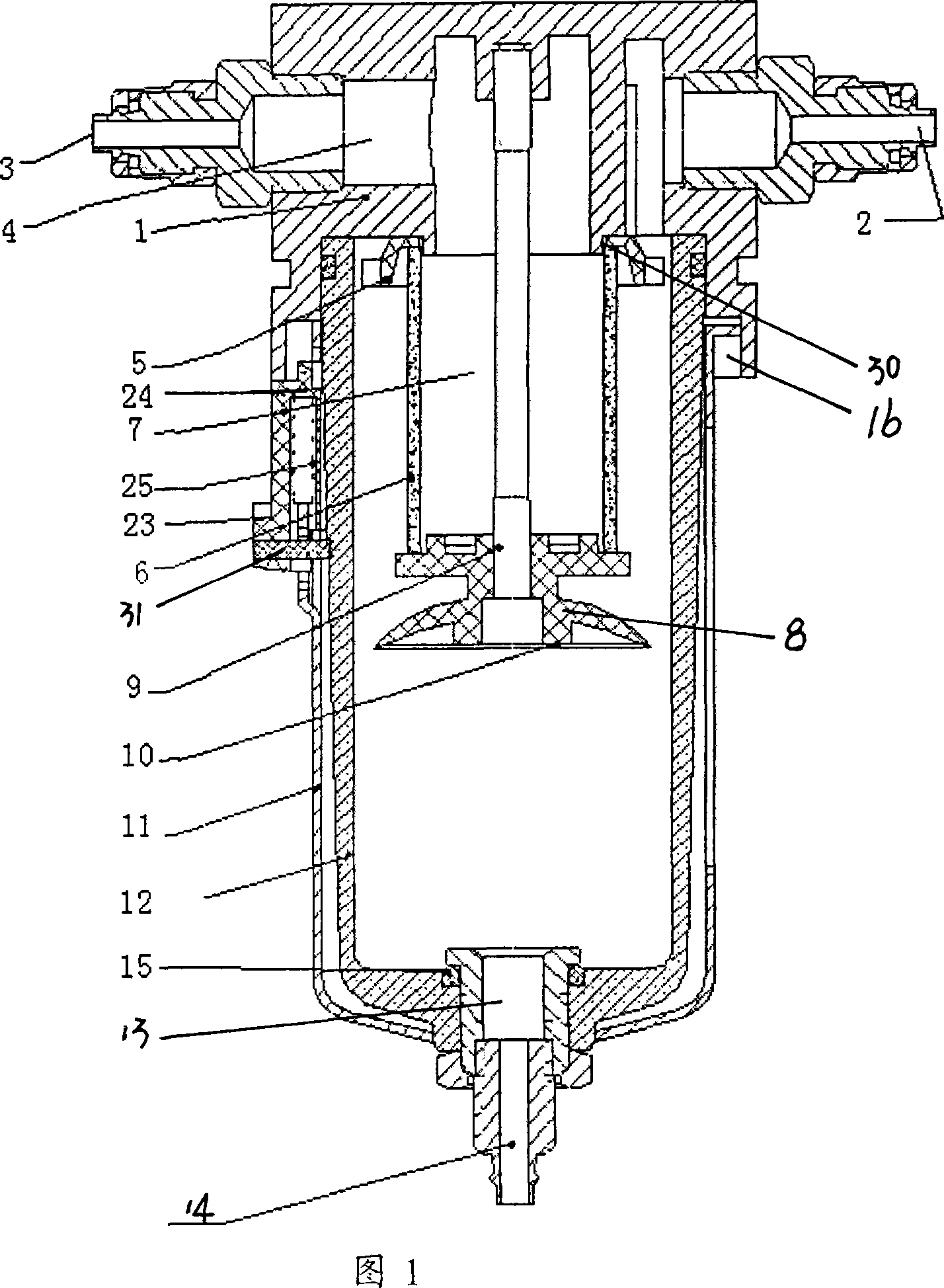
[0011] As shown in FIG. 1 , an air inlet 2 and an air outlet 3 are provided on the upper cover 1 of the oil-gas separator, and the air outlet cavity 4 in the upper cover 1 communicates with the air outlet 3 . A filter element holder 5 is provided on the air outlet cavity wall 30 in the upper cover 1 , and a filter element 6 is arranged on the filter element holder 5 . The filter element 6 is a hollow structure to form a cavity 7 for filtering and separating the gas, and the cavity 7 in the filter element 6 communicates with the gas outlet cavity 4 in the upper cover 1 . The filter element 6 can be cup-shaped, and the filter element mouth "cup mouth" is connected with the filter element holder 5 or the upper cover 1 . It can also be "cylindrical". The filter element 6 of this embodiment adopts a "cylindrical shape". One end opening of the filter element 6 is connected to the filter element holder 5, and the other end opening is connected to the filter element cover 8. The conne...


PUM


Abstract

The invention discloses a novel oil-gas separator. The invention comprises an upper cover and a casing connected with the upper cover. The invention is characterized in that an oil collecting cup is arranged in the casing, a cavity filter element is arranged in the oil collecting cup, the cavity filter element is connected with the upper cover, the cavity in the filter element is communicated with the air outlet cavity in the upper cover, the air outlet cavity is communicated with an air outlet opening, the air inlet opening on the upper cover is communicated with the inner cavity of the oil collecting cup, and the inner cavity of the oil collecting cup is separated from the cavity in the filter element via the filter element. The device is arranged on an air exhaust pipeline of a variable speed device, a transfer case, and a bridge, etc., and the oil outlet opening of the oil collecting cup leads the lubricating oil separated to be reflowed to parts of a main speed reducer, a mechanical transmission and a wheel side speed reducer after being filtered by a filter. Thereby the loss caused by the lubricating oil gasification is effectively reduced. The assembling and disassembling of the oil-gas separator on the pipeline are convenient, and the structure is simple. The default that the existing vehicle has no a gasification lubricating oil separation, as well as recovery device is made up.

Description

technical field [0001] The invention belongs to an oil-gas separation device, in particular to an oil-gas separation device for a vehicle after lubricating oil gasifies and enters an exhaust pipe. Background technique [0002] After running at high speed for a long time, the temperature of each assembly of the car will become higher, causing the lubricating oil to volatilize and generate oil gas. If the generated oil and gas are not separated, the lubricating oil will be discharged together with the gas. One is to reduce the lubricating oil inside the assembly, and the other is to affect the performance of the whole vehicle due to oil leakage. And now there is no device for separating and recovering lubricating oil and gas on vehicles. Vehicles other than off-road vehicles usually adopt a vent plug with a one-way valve structure. In foreign countries, the air outlet pipe is directly connected to the atmosphere and the air filter is connected, but both have disadvantages: ne...

Claims


Application Information

Patent Timeline
IPC IPC(8): F01M13/04F01M11/08B01D46/24
Inventor 黄松汪振晓施辉良
Owner DONGFENG MOTOR CORP HUBEI
Why Eureka
Try Eureka