High temperature fluidized bed combustion device

A technology of high-temperature fluidized bed and combustion device, which is applied in the direction of fluidized bed combustion equipment, fuel burned in a molten state, and combustion methods, etc. It can solve problems such as low combustion efficiency, increased investment cost, difficulty in operation, and complex system, and achieves Extended residence time, improved lateral mixing characteristics, reduced complexity effects

Inactive Publication Date: 2008-03-19
SHANGHAI JIAO TONG UNIV
View PDF1 Cites 2 Cited by
  • Summary
  • Abstract
  • Description
  • Claims
  • Application Information

AI Technical Summary

Problems solved by technology

This patent is a very practical and valuable improved circulating fluidized bed device for difficult-to-combustible coal, but due to the addition of fly ash collectors, return controllers, and pneumatic conveying injectors, the system is complicated and greatly increases investment costs and operation. Although it is beneficial to reduce the carbon content of fly ash, it cannot fundamentally solve the problem of low combustion efficiency

Method used


Image

  • High temperature fluidized bed combustion device

Examples


Embodiment Construction

[0015] The embodiments of the present invention are described in detail below in conjunction with the accompanying drawings: this embodiment is implemented on the premise of the technical solution of the present invention, and detailed implementation methods and specific operating procedures are provided, but the protection scope of the present invention is not limited to the following the described embodiment.

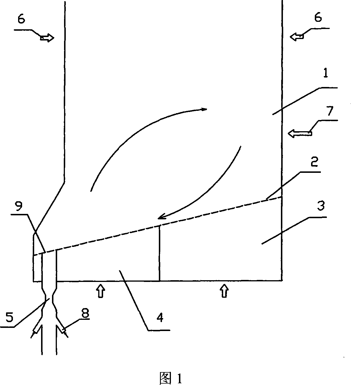
[0016] As shown in Figure 1, this embodiment includes: furnace 1, inclined non-uniform air distribution plate 2, low-speed primary air chamber 3, high-speed primary air chamber 4, winnowing slag discharge pipe 5, secondary air inlet 6, feed port 7. Sorting air duct 8, slag discharge port 9, inclined non-uniform air distribution plate 2 is installed at the bottom of furnace 1, and low-speed primary air chamber 3 and high-speed primary air chamber 4 are installed under the inclined non-uniform air distribution plate 2. The air chamber 3 is located below the low end of t...


PUM


Abstract

The invention relates to a high temperature fluid bed combustion device in the energy resource field. The device comprises a furnace, an inclined uneven air distribution plate, a low speed primary air chamber, a high speed primary air chamber, an air classification deslagging pipe, a secondary air inlet opening, a material inlet opening, classifying air pipes and a deslagging opening. The connection relations are that the inclined uneven air distribution plate is arranged at the bottom of the furnace, the low speed primary air chamber and the high speed primary air chamber are arranged under the inclined uneven air distribution plate, the low speed primary air chamber is positioned under the lower end position of the inclined uneven air distribution plate, the high speed primary air chamber is positioned under the higher end position of the inclined uneven air distribution plate, the secondary air inlet opening is arranged on the upper part of the furnace, the material inlet opening is arranged on the furnace wall close to the low speed primary air chamber, the deslagging opening is positioned at the crossing position of the lower end of the inclined uneven air distribution plate and the furnace wall, one end of the air classification deslagging pipe is connected with the deslagging opening, the classifying air pipes are arranged on the two sides of the air classification deslagging pipe, and the classifying air pipes are communicated with the air classification deslagging pipe. The device of the invention is simple, the investment expense is low, the reliability is high, the overall combustion reaction speed is enhanced, and the fly ash carbon content is reduced.

Description

technical field [0001] The invention relates to a device in the technical field of combustion equipment, in particular to a high-temperature fluidized bed combustion device. Background technique [0002] As an advanced combustion technology, the fluidized bed has been widely used because of its strong adaptability to coal types and favorable pollutant control. Because the furnace temperature of the fluidized bed is lower than that of the pulverized coal furnace, only 850-900°C, the bed material is usually circulated repeatedly in it, that is, the circulating fluidized bed method. It is generally believed that the combustion efficiency is close to the level of the pulverized coal furnace with the same capacity. Extensive practice of burning highly reactive fuels such as lignite does show that circulating fluidized bed boiler fly ash has a low carbon content. But in fact, the vast majority of circulating fluidized bed boilers in my country use difficult-to-combustible coals, ...

Claims


Application Information

Patent Timeline
Patent Type & Authority Applications(China)
IPC IPC(8): F23C10/00F23C10/24
Inventor 范浩杰章明川施善彬
Owner SHANGHAI JIAO TONG UNIV
Why Eureka
Try Eureka