Supercharge Your Innovation With Domain-Expert AI Agents!

Heat pipe type solar thermal-collecting tube

A solar collector tube and heat pipe type technology, applied in the directions of solar collectors, solar thermal energy, solar thermal power generation, etc., can solve the problems of burst tubes, large circular cavity space, inability to heat the heat conduction medium, etc., to improve the effective utilization rate, Fast hot start and low cost effect

Inactive Publication Date: 2008-03-19
张永平
View PDF0 Cites 19 Cited by
  • Summary
  • Abstract
  • Description
  • Claims
  • Application Information

AI Technical Summary

Problems solved by technology

[0003] In order to ensure the collection effect of sunlight, the existing double-vacuum glass heat pipe heat collector adopts the method of coating on the outside of the circular tube, but the circular tube method cannot quickly transfer a small amount of heat transfer medium due to the large space of the round cavity. Fully heated, even if the heat transfer medium can be quickly and fully heated, because the volume of the heat release part only accounts for one-tenth of the entire cavity volume, it is impossible to efficiently transfer heat to the water in the water tank
In the existing technology, if the cavity of the heat-absorbing part is reduced, the ability to collect sunlight will be greatly reduced. If the amount of heat-conducting medium is increased, the phenomenon of pipe burst will occur due to heating and expansion.

Method used


Image

  • Heat pipe type solar thermal-collecting tube
  • Heat pipe type solar thermal-collecting tube
  • Heat pipe type solar thermal-collecting tube

Examples


Embodiment 1

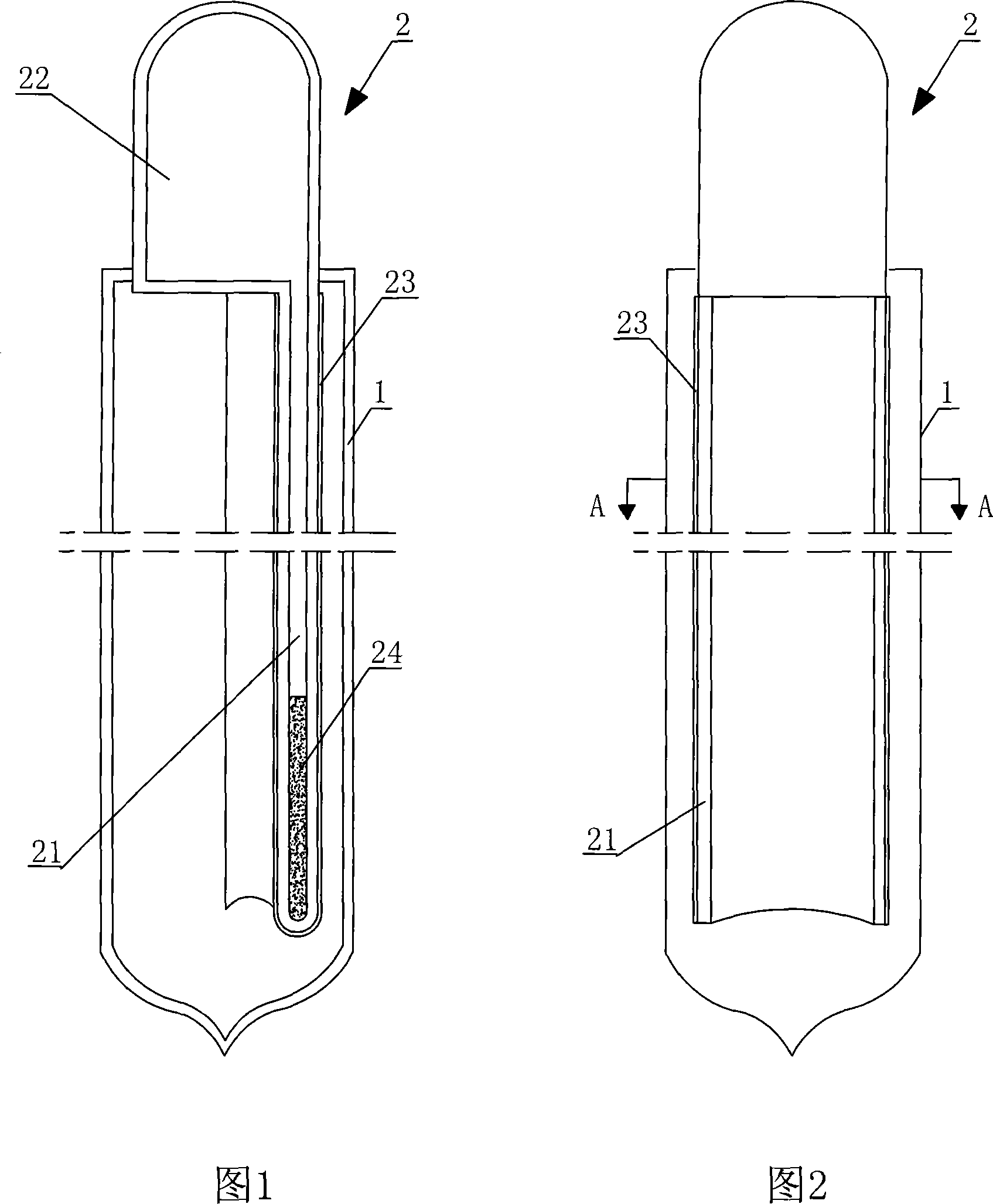
[0042] Referring to Fig. 1-3, a heat pipe type solar collector tube is composed of an outer tube 1 and an inner heat pipe 2, the inner heat pipe 2 is composed of a heat absorbing part 21 and a heat releasing part 22, and the inner heat pipe 2 The heat-absorbing part 21 of the inner heat pipe 2 is arranged in the outer casing 1, and the cross-section of the heat-absorbing part 21 of the inner heat pipe 2 is a circular arc-shaped double-layer structure provided with a hollow inner cavity, and the heat-releasing part 22 of the inner heat pipe 2 is clamped It is located outside the outer casing 1, and the joint between the inner heat pipe 2 and the outer casing 1 is sealed. The outer surface of the heat-absorbing part 21 of 2 is coated with a solar absorbing coating 23, and the inner cavity of the inner heat pipe 2 is provided with a heat-conducting medium 24.

[0043] The heat absorbing part 21 of the inner heat pipe 2 has a double-layer structure with a circular arc-shaped cross...

Embodiment 2

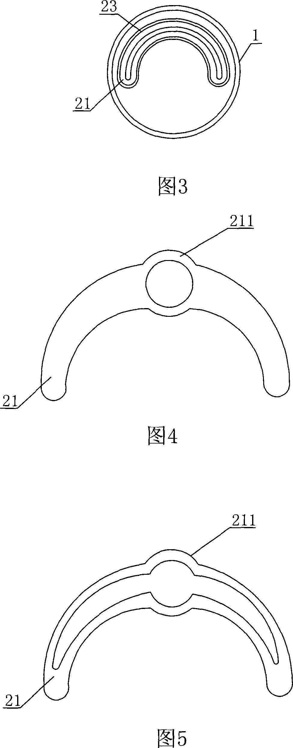
[0051] Referring to shown in Fig. 4, a kind of heat pipe type solar collector tube, it differs from Embodiment 1 in that:

[0052] The heat absorbing part 21 of the inner heat pipe 2 is provided with a double-layer structure with a circular arc-shaped cross-section and a hollow inner cavity, and a hollow inner cavity 211 with a circular cross-section is provided.

[0053] The heat absorbing portion 21 of the inner heat pipe 2 has an arc-shaped cross section and a double-layer structure with a hollow inner cavity, and the distance between inner walls is 0.1 mm.

[0054] The heat release portion 22 of the inner heat pipe 2 has a length of 5 cm.

[0055] The shape of the inner chamber cross-section of the heat releasing part 22 of the inner heat pipe 2 is arc shape.

[0056] The shape of the cross-section of the outer sleeve 1 is a garden arc.

Embodiment 3

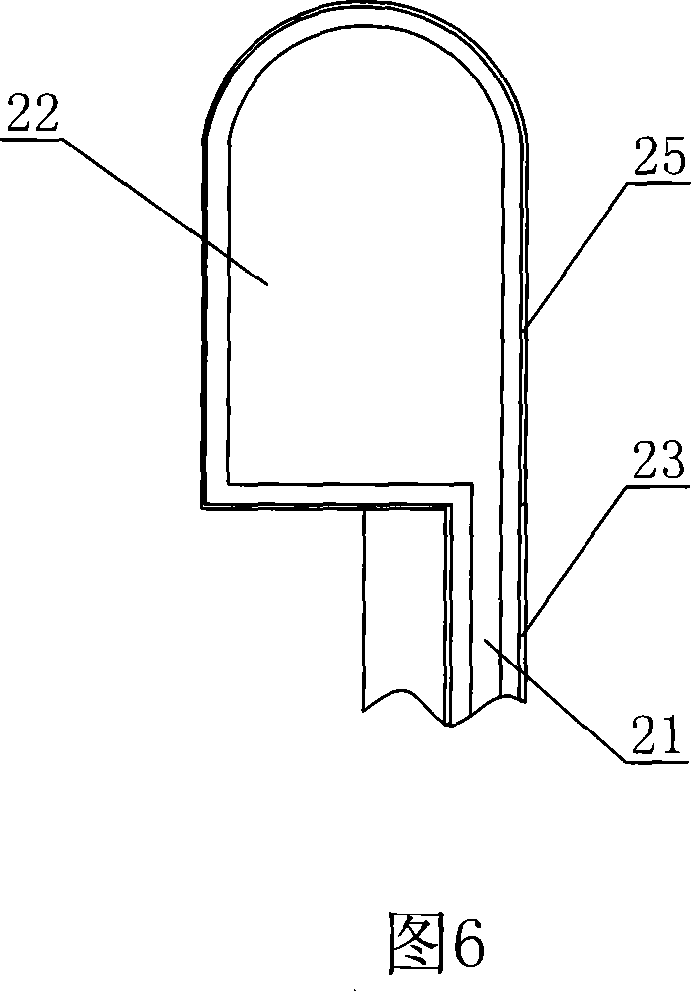
[0058] Referring to Fig. 5-6, a kind of heat pipe type solar collector tube differs from Embodiment 1 in that:

[0059] The cross-section of the heat absorbing portion 21 of the inner heat pipe 2 may be a combination of a hollow arc-shaped inner cavity and a hollow circular inner cavity.

[0060] The material of the inner heat pipe 2 is plastic.

[0061] The heat conducting medium 24 is a composite inorganic superconducting heat medium.

[0062] The surface of the inner cavity of the heat absorbing part 21 of the inner heat pipe 2 is coated with a solar absorbing coating 24 .

[0063] The outer surface of the heat release part 22 of the inner heat pipe 2 is coated with an anti-scaling thermal conductive coating 25 .

[0064] The heat-absorbing part 21 of the inner heat pipe 2 has an arc-shaped cross-section and a double-layer structure with a hollow inner cavity, and the distance between inner walls is 3 mm.

[0065] The heat release portion 22 of the inner heat pipe 2 has ...


PUM

PropertyMeasurementUnit
Lengthaaaaaaaaaa
Lengthaaaaaaaaaa
Lengthaaaaaaaaaa

Abstract

The invention relates to a heat tube type solar energy collector tube, which consists of an outer bushing, and an inner heat pipe. The inner heat pipe consists of a heat absorption part and a heat elimination part, the heat absorption part and the heat elimination part are integral, the heat absorption part of the inner heat pipe is arranged in the outer bushing, the cross section of the heat absorption part of the inner heat pipe is a circular arc shape two-layer structure which is provided with a cavity, the heat elimination part of the inner heat pipe is clipped and fixed outside the outer bushing, the seal connection is arranged at the clipped and fixed connecting position of the heat absorption part and the heat elimination part, the inner heat pipe is arranged on the outer wall in the outer bushing, and a vacuum state is between the outer wall and the cavity wall of the inner pipe of the outer bushing, a solar energy absorption coating is plated on the external surface of the heat absorption part of the inner heat pipe, and the cavity of the inner heat pipe is provided with a heat-conducting medium; the invention saves the raw material and the energy source, the thermal efficiency is high, the warm start is fast, the pipe can not burst, the pipe can not be cracked in winter, the applicable districts are wide, the thermal efficiency can not be attenuated after long using, and the secure performance is high.

Description

technical field [0001] The invention relates to a heat pipe type solar heat collecting pipe. Background technique [0002] At present, the most widely used solar collector tube is the double-layer glass single-vacuum water-flowing heat collector tube, which is widely used because of its early technology and low cost, but it has many disadvantages: such as low heat utilization rate , waste water resources, easy to generate scale; and once scale is generated, the efficiency of the heat collecting tube will drop sharply, the tube will explode due to uneven cold and heat, it will be easy to freeze and crack in cold winter, and the safety will be poor. In response to these shortcomings, the principle of heat pipes has been introduced since the 1990s. The corresponding technologies are: double vacuum glass heat pipes, vacuum glass metal heat pipes, double-layer glass single vacuum + metal heat pipes. The last two technologies with metal heat pipes have initially formed industrial...

Claims


Application Information

Patent Timeline
IPC IPC(8): F24J2/05F24J2/32F24J2/46F24S10/40F24S10/95
CPCY02E10/44F24S10/45F24S10/95
Inventor 张永平
Owner 张永平
Features
  • R&D
  • Intellectual Property
  • Life Sciences
  • Materials
  • Tech Scout
  • Unparalleled Data Quality
  • Higher Quality Content
  • 60% Fewer Hallucinations
Learn More