
Fire vortex experimental facility

An experimental device, fire whirlwind technology, applied in the direction of measuring devices, aerodynamic tests, instruments, etc., can solve problems such as high temperature, casualties and property losses, increase the heat release rate of fire, etc., to increase diversity and improve operation The effect of flexibility

Inactive Publication Date: 2008-03-19
UNIV OF SCI & TECH OF CHINA
View PDF0 Cites 11 Cited by
  • Summary
  • Abstract
  • Description
  • Claims
  • Application Information

AI Technical Summary

Problems solved by technology

The fire whirlwind burns fast and the temperature is high. Once it occurs, the heat release rate of the fire will be increased, it is difficult to suppress and extinguish, and the risk factor and destructive power of the fire will rise sharply. Once the fire whirlwind occurs, it will cause casualties and serious damage. property damage
Due to the sudden change of the fire head and heat flow direction during the fire whirlwind process, it will have a serious impact on the life safety of fire fighters
Although people have studied the fire whirlwind since the 1960s and 1970s, and have attracted people's attention in recent years, and have achieved certain results in theory and experiment, but so far have not fully grasped its laws, such as the fire whirlwind. The distribution of temperature field, its occurrence and development prediction, and how to take effective suppression measures, etc.
In the existing technical data, there is no report about the special experimental device in this regard

Method used


Image

  • Fire vortex experimental facility
  • Fire vortex experimental facility
  • Fire vortex experimental facility

Examples


Embodiment Construction

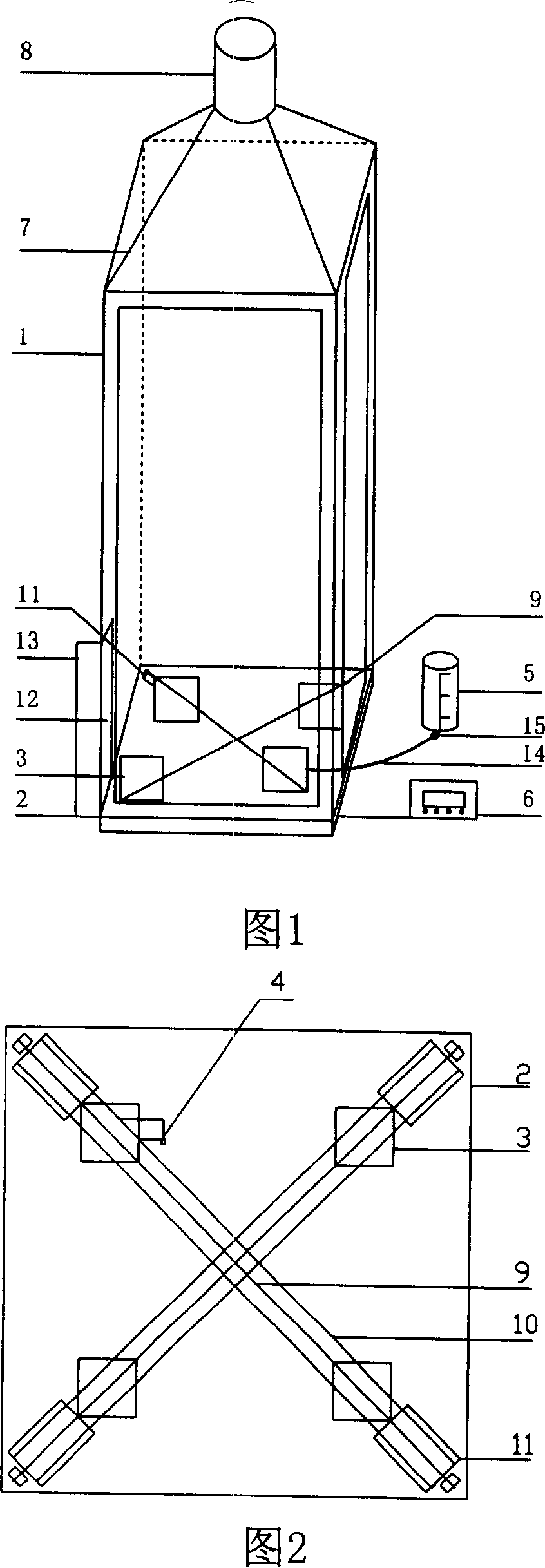
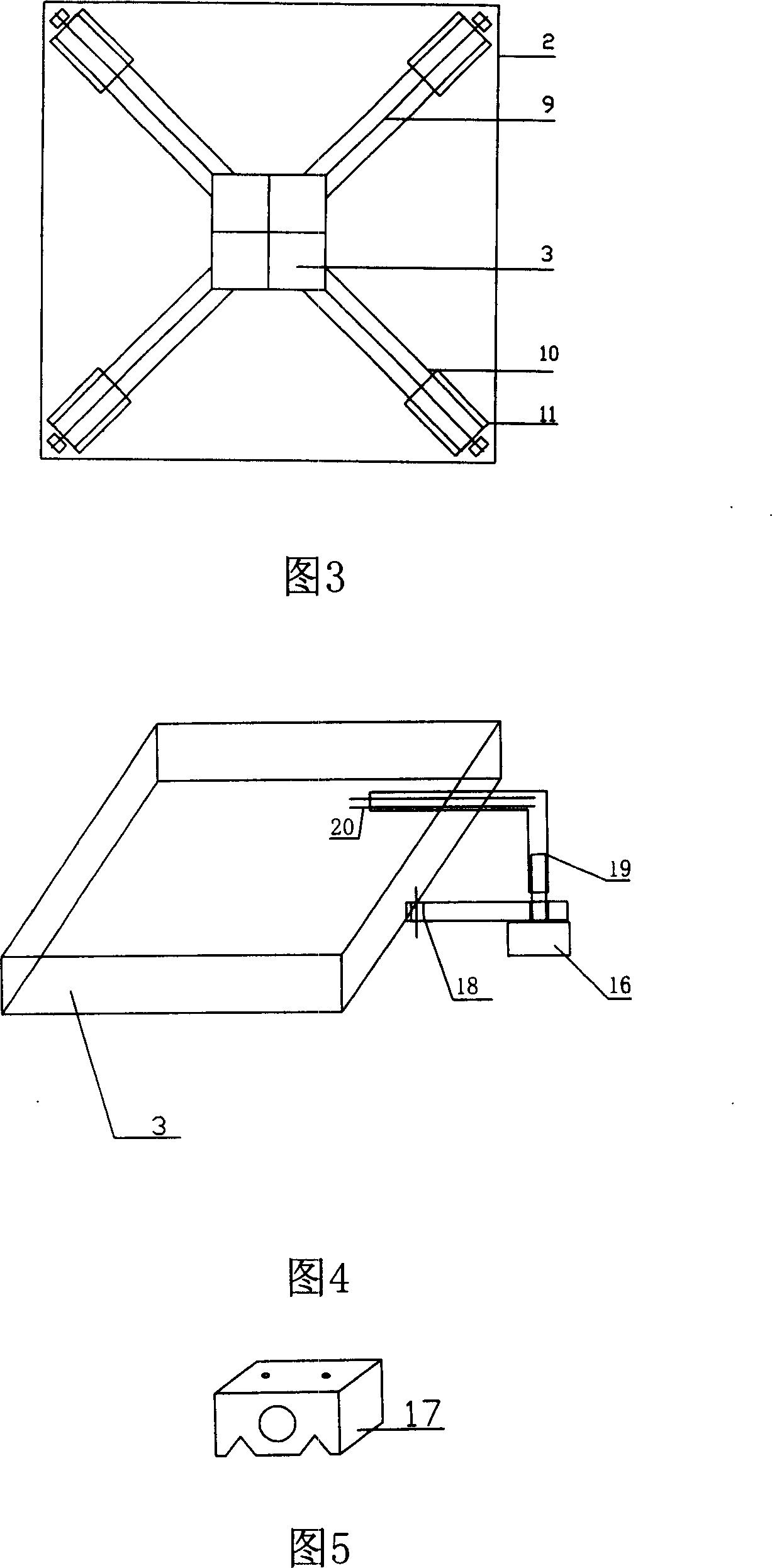
[0016] Referring to Fig. 1, the housing 1 and the base 2 are both square, and the two are closely connected to form a square cylindrical inner space. The four sides of the housing 1 are made of fire-resistant glass, which is convenient for observation during the experiment. The four corners and four top edges are made of stainless steel or other metals to fix the fire-resistant glass on the side and make it have sufficient strength. There are respectively tangential air inlets 12 near the stainless steel column on the right side of each side, and the air inlet door 13 is installed with the stainless steel column as a shaft, which can easily adjust the opening of the air inlet. During the test, under the influence of buoyancy, air enters tangentially, driving the flow field to rotate, thus generating a fire whirlwind. A smoke collecting hood 7 and a smoke exhaust pipe 8 leading to the outside are installed on the top of the housing to exhaust the smoke. The base 2 is made of ...


PUM


Abstract

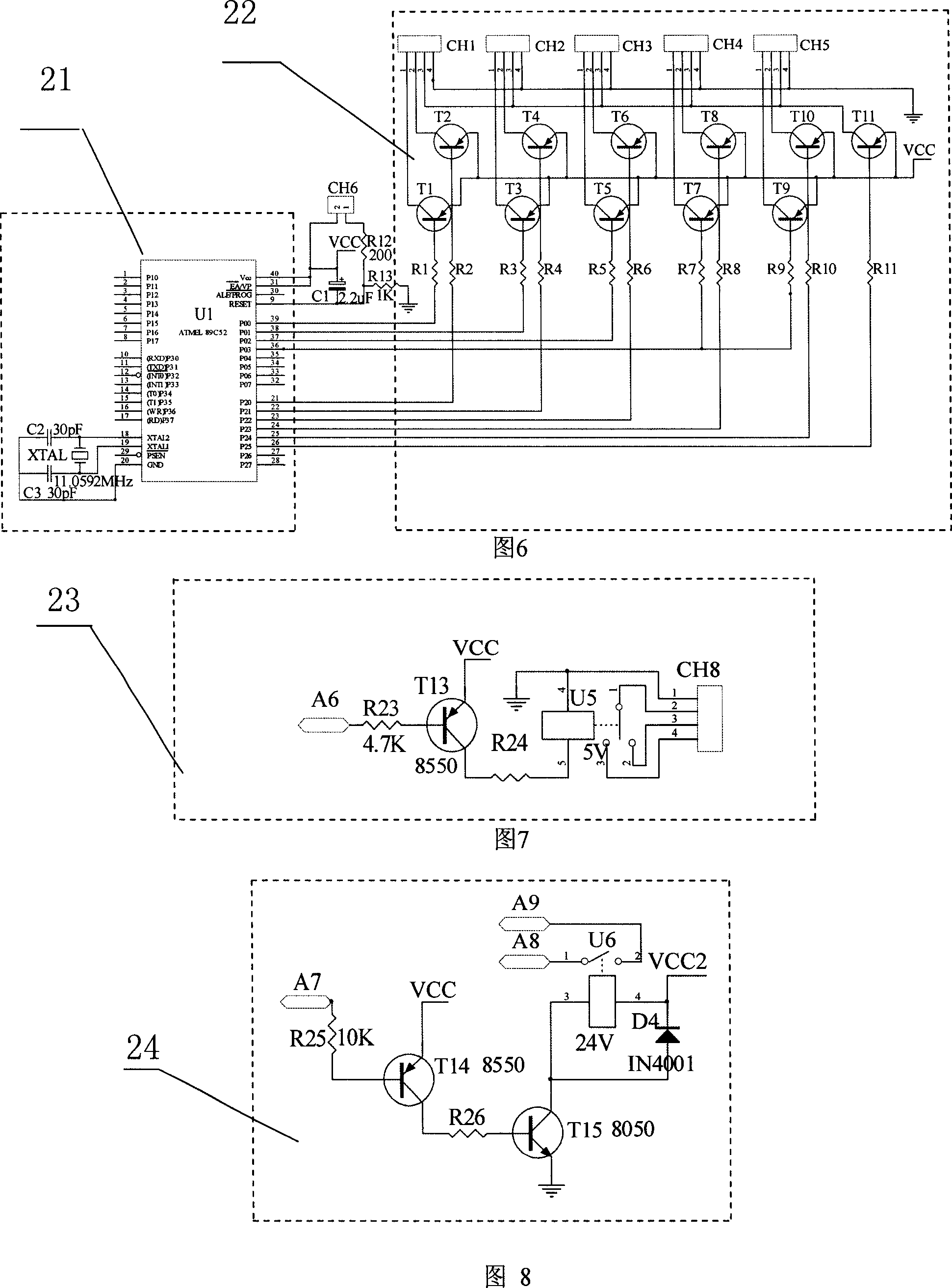
The present invention belongs to the technical field of the fire safety, in particular to a simulating experiment device for inflammation in a disaster. The device consists of a smoke exhaust pipeline, flaming cells, a fuel feeding system and a control system, wherein, the smoke exhaust pipeline comprises a rectangular column shaped casing, which is closely integrated to a base seat to form a rectangular column shaped inner space; the middle of the top has the smoke exhaust pipeline; a lateral wall of the inner space is provided with an air inlet which can be opened or closed; with being respectively arranged on four slider blocks, the flaming cells contact closely by twos when the slider blocks move inwards; the fuel feeding system consists of a fuel container arranged out of the casing and a hosepipe connected with the casing; the control system consists of a single-chip microcomputer and the operation system thereof controlling the feeding of the fuel, the moving of the flaming cells and the switching of an ignition device. In the experiment device, the four flaming cells of the same size are arranged on a plane and can be controlled to move flexibly to form a large flaming cell, therefore, the conditions and the rules for forming fire whirlwinds by flames in a plurality of small flaming cells can be studied, and the fire whirlwind experiment of a single large flaming cell can also be performed.

Description

Technical field: [0001] The invention belongs to the technical field of fire safety, and in particular relates to an experimental simulation device for disaster combustion. Background technique: [0002] When a forest fire or a building group fire occurs, the combustion causes high and low air pressure, and a strong convective fire phenomenon of a rotating flame will appear. When the intensity of the rotating flame is large enough, a fire whirlwind is formed. At this time, the flame height becomes order of magnitude increase. The fire whirlwind burns fast and the temperature is high. Once it occurs, the heat release rate of the fire will be increased, it is difficult to suppress and extinguish, and the risk factor and destructive power of the fire will rise sharply. Once the fire whirlwind occurs, it will cause casualties and serious damage. property damage. Due to the sudden change of the fire head and heat flow direction during the fire whirlwind process, it will have a ...

Claims


Application Information

Patent Timeline
Patent Type & Authority Applications(China)
IPC IPC(8): G09B25/00G01M9/00
Inventor 姚斌秦俊刘乃安李权威安江涛
Owner UNIV OF SCI & TECH OF CHINA
Learn More