
Grating aligner

A collimator and grating technology, applied in the field of medical equipment, can solve the problems of the performance and quality discount of the intensity-modulated conformal field, the influence of the follow-up speed, and the poor treatment efficiency, and achieves fast image follow-up speed, high degree of automation, and universal use. good effect

Inactive Publication Date: 2008-03-19
王乔生
View PDF0 Cites 5 Cited by
  • Summary
  • Abstract
  • Description
  • Claims
  • Application Information

AI Technical Summary

Problems solved by technology

[0005] However, the motorized multi-leaf collimator is composed of many independent tungsten alloy sheets and micro-motors overlapping together. First of all, it is limited by its structure and size, and the field of view cannot be exactly consistent with the shape of the tumor. The conformal field is obviously very rough. ;In addition, the thin slices need to move flexibly, therefore, the blades cannot be too close together, which will inevitably cause the leakage of rays through the gap between the blades, which greatly reduces the performance and quality of the intensity-modulated conformal field; Third, the tungsten alloy blade is driven by a stepping motor, and it takes time to move. In the image-guided intensity modulation conformal, it is impossible to adopt a more advanced way of beam following the movement of the organ. Only the treatment bed following technology can be used. The corresponding following speed will be affected
[0006] As mentioned above, the use of multi-radiation sources and the use of multi-leaf grating collimators will make the structure of the radiation therapy system complex, and its image follow-up rate is low, making the treatment efficiency poor; and the safety of radiotherapy is not high, and the treatment effect is poor

Method used


Image

  • Grating aligner
  • Grating aligner
  • Grating aligner

Examples


Embodiment Construction

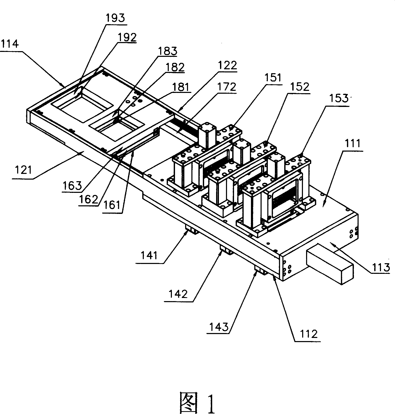
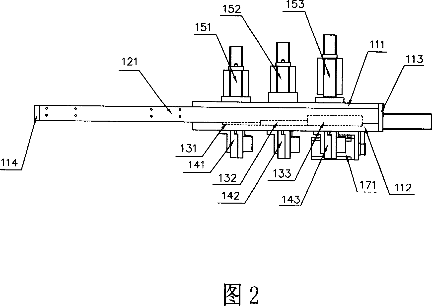
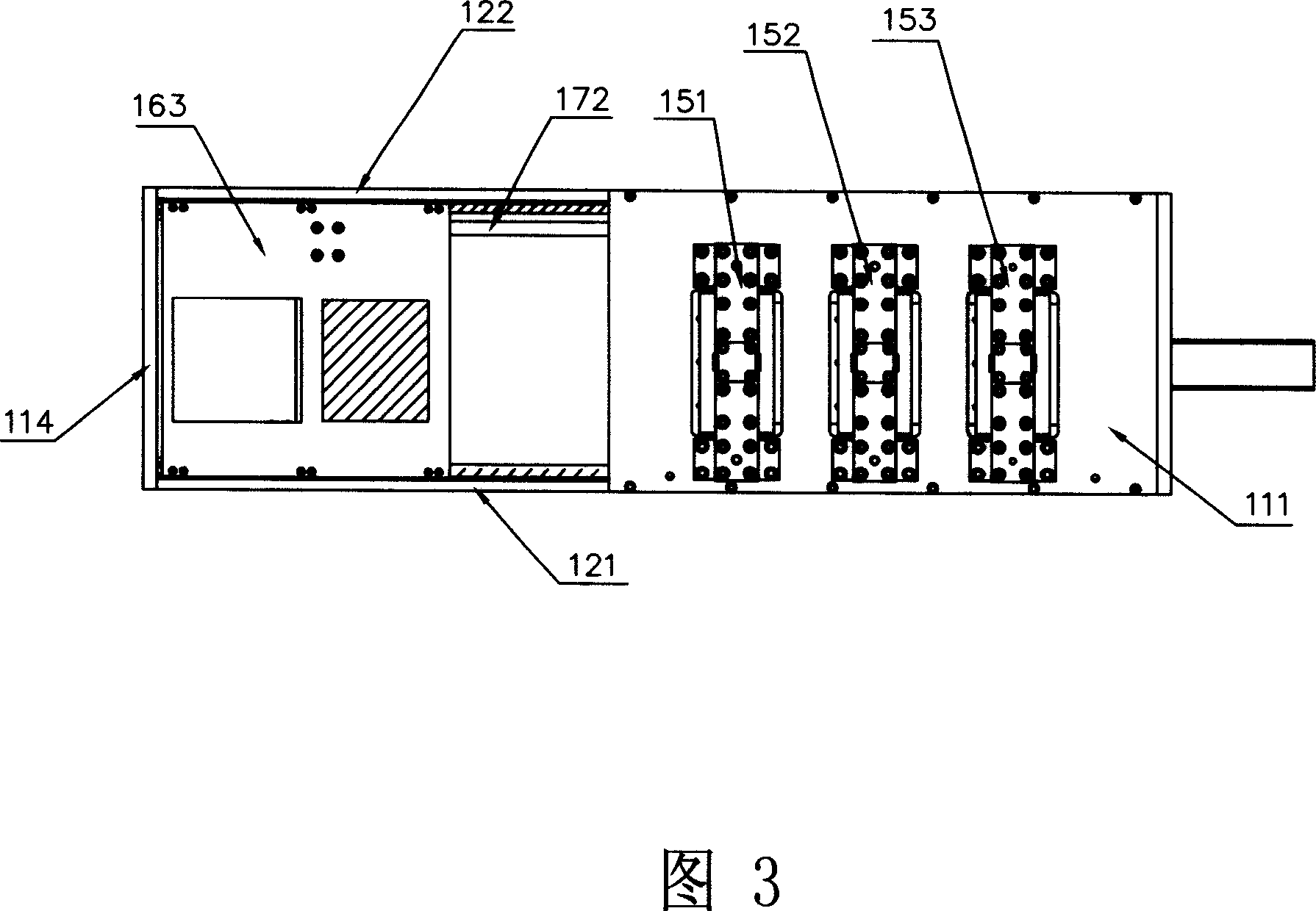
[0019] Please refer to Fig. 1, 2, 3 and 4 in conjunction with, the grating collimator provided by the present invention comprises upper fixed plate 111, lower fixed plate 112, rear fixed plate 113, limit plate 114, guide rail 121,122, magazine device 131 , 132,133, needle pushing device 141,142,143, needle withdrawal device 151,152,153, sub-grating transport device 161,162,163, motor 171, screw mandrel 172.

[0020] The grating collimator provided in this embodiment has three sets of needle withdrawal devices, and the numbers in the drawings are respectively 151, 152 and 153. Correspondingly, there are three needle withdrawal operation holes on the upper fixing plate 111, and the needle withdrawal devices 151, 152 and 153 are horizontally fixed side by side above the upper fixing plate 111, and are respectively located at the three withdrawal operation holes. The grating collimator provided in this embodiment has three sets of magazine devices. The magazine devices 131 , 132 ...


PUM


Abstract

The invention discloses a grating collimator used for radiotherapy, which comprises an upper fixed plate, a lower fixed plate, a rear fixed plate, a magazine chamber, a needle-pushing device, a needle-withdrawing device, a guide rail, a grating delivery device, and a driving device. The needle-withdrawing device is fixed above the upper fixed plate. The magazine chamber is arranged on the lower fixed plate. The needle-pushing device is fixed under the lower fixed plate and positioned right below the magazine chamber. The needle-withdrawing device is positioned right above the magazine chamber. An operating space is formed between the upper and the lower fixed plates. The guide rail is arranged between the upper and the lower fixed plates and partially extends outside the upper and the lower fixed plates. The grating delivery device is arranged on the guide rail and connected with the driving device. The grating delivery device is driven by the driving device to move along the guide rail between the operating space and the exterior thereof. The invention has the advantages of good versatility, high automation degree, easy use and high efficiency and can meet the requirements of high accuracy and rapid image following rate in the field of radiotherapy.

Description

technical field [0001] The invention relates to a medical device, in particular to a grating collimator for radiotherapy. Background technique [0002] Medical radiotherapy equipment generally includes a central processing control device, a treatment bed, a treatment host, a power supply and signal transmission device, and an electric cabinet control device. Among them, the treatment host includes a rotating cylinder, which is equipped with an X-ray generating device for spiral tomography and an image acquisition and receiving device, as well as a radiation source, a grating and a collimator device for radiation therapy, and a device for detecting radiation therapy. Dose detection devices for the effect and progress of radiotherapy, etc. [0003] The grating and its collimator device are key components of radiotherapy equipment, which are related to the overall structural arrangement of the radiotherapy system and the effect and efficiency of radiotherapy. [0004] The rad...

Claims


Application Information

Patent Timeline
IPC IPC(8): G21K1/02G21K1/04A61N5/10
Inventor 郝镇熙王乔生李发军
Owner 王乔生
Learn More