A hydrothermal processing method for fuel battery current field

A hydration treatment and fuel cell technology, which is applied to fuel cells, fuel cell parts, solid electrolyte fuel cells, etc., can solve problems such as uneven gas distribution in the battery pack, water accumulation, MEA flooding, etc., to achieve The effect of reducing MEA flooding phenomenon, reducing water management pressure, and improving water increasing performance

Inactive Publication Date: 2008-03-19
SUNRISE POWER CO LTD
View PDF0 Cites 1 Cited by
  • Summary
  • Abstract
  • Description
  • Claims
  • Application Information

AI Technical Summary

Problems solved by technology

[0003] Since the fuel cell is a complex chemical reaction process when it is working, there are problems of heat balance and water balance; among them, water management in the operation of the fuel cell is a problem that is difficult to control
When the amount of water in the reaction gas is slightly less (low relative humidity), the proton exchange membrane will dry out and the resistance will increase, makin

Method used


Image

  • A hydrothermal processing method for fuel battery current field
  • A hydrothermal processing method for fuel battery current field
  • A hydrothermal processing method for fuel battery current field

Examples


Example Embodiment

[0021] Example 1

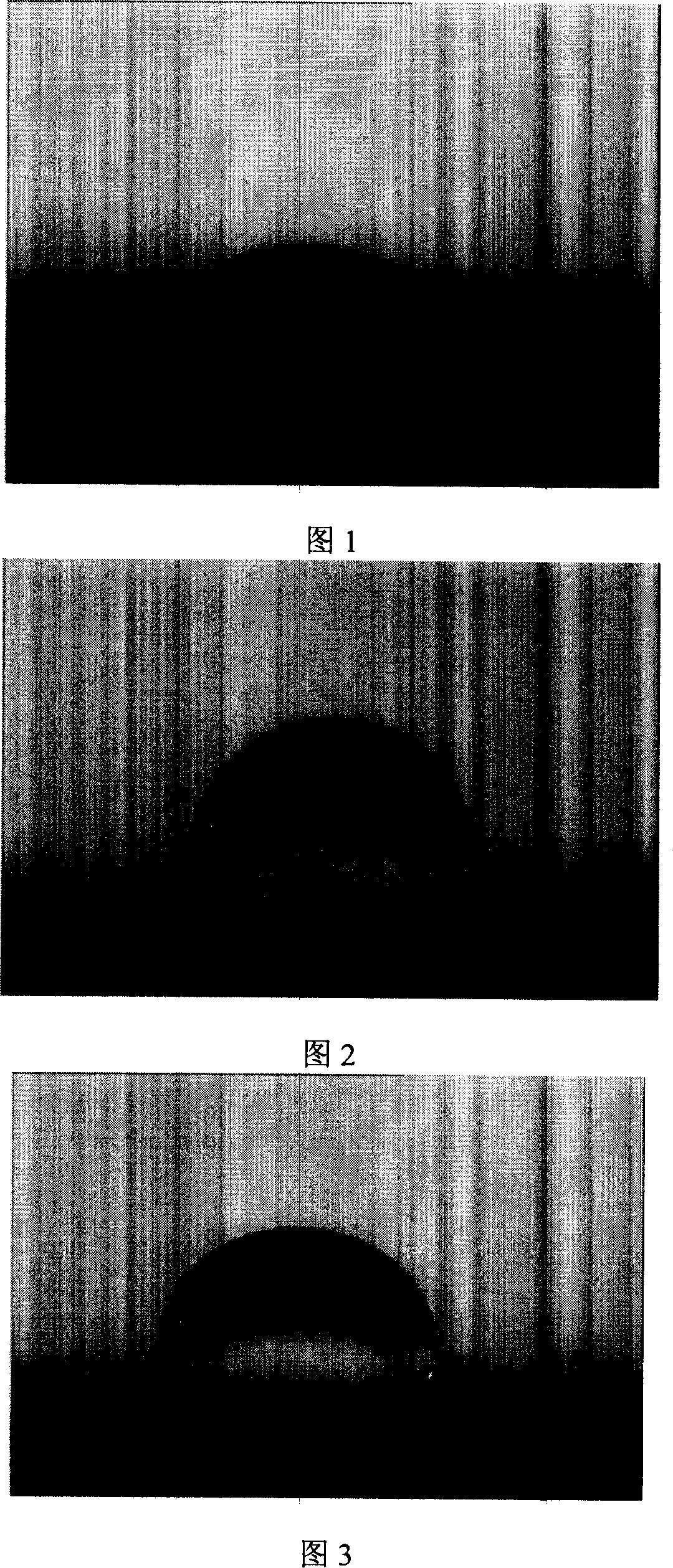
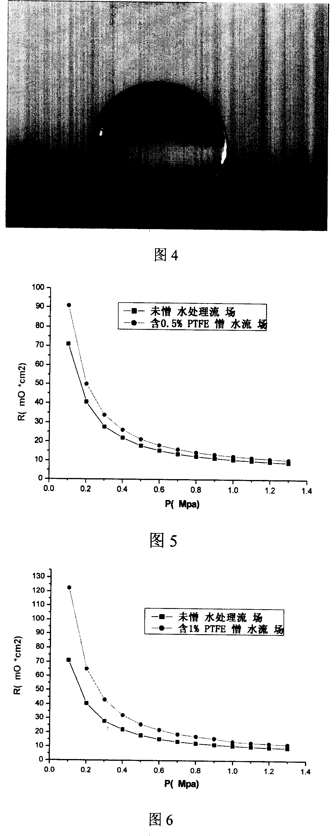
[0022] According to the method of the present invention, 60% PTFE emulsion is used to configure 2% PTFE solution, and the expanded graphite flow field plate is soaked once or several times, so that the content of tetrafluoride in the flow field is controlled at 0.5%. Then put the soaked flow field into a vacuum oven and bake and cure at 350° C. for 2 hours. Finally, the boss part of the surface of the flow field is polished to remove the non-conductive substance on the surface. The surface contact angle (Figure 1 and Figure 2) and contact resistance (Figure 5) of the flow field plate after hydrophobic treatment were tested. The results show that the resistance of the flow field does not increase much, but the water increase performance of the flow field is significantly improved.

Example Embodiment

[0023] Example 2

[0024] According to the method of the present invention, 60% PTFE emulsion is used to prepare 5% PTFE solution, and the expanded graphite flow field plate is soaked once or more times, so that the tetrafluoroethylene content in the flow field is controlled at 1%. Then put the soaked flow field into a vacuum oven and bake and cure at 400° C. for 1 hour. Finally, the boss part of the surface of the flow field is polished to remove the non-conductive substance on the surface. The surface contact angle (Fig. 3) and contact resistance (Fig. 6) of the flow field plate after hydrophobic treatment were tested. The results show that the resistance of the flow field does not increase much, but the water increase performance of the flow field is significantly improved.

Example Embodiment

[0025] Example 3

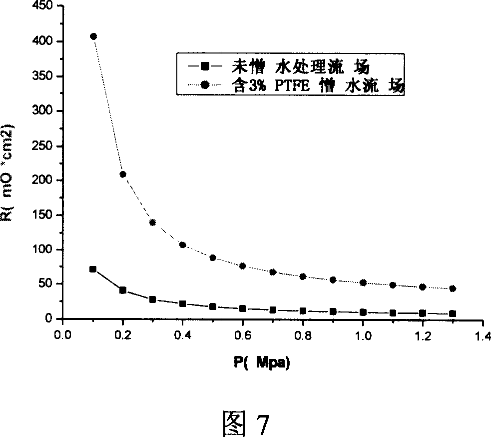
[0026] According to the method of the present invention, 60% PTFE emulsion is used to configure 5% PTFE solution, and the expanded graphite flow field plate is soaked once or more times, so that the tetrafluoroethylene content in the flow field is controlled at 3%. Then put the soaked flow field into a vacuum oven and bake and cure at 400° C. for 1 hour. Finally, the boss part of the surface of the flow field is polished to remove the non-conductive substance on the surface. The surface contact angle (Figure 4) and surface contact resistance (Figure 7) of the flow field plate after hydrophobic treatment were tested. The results show that 3% PTFE in the flow field will lead to an increase in the resistance of the flow field plate.


PUM


Abstract

A hydrophobic treatment method for fuel cell flow field is provided, which comprises the flow field surface is immersed with a hydrophobic agent to solidify at high temperature to allow hydrophobic agent to bond with the flow field firmly, lastly the hydrophobic agent is polished and removed from the surface of protrusions of the flow field surface. The method can suppress the increase of contact resistance, impart the fuel cell flow field with hydrophobic function, promote the discharge of liquid water during the operation of the fuel cell, and prevent the drowning phenomena of MEA during the operation of the fuel cell. The flow field treated with this method can reduce the water management pressure during the operation of the fuel cell and increase the utilization rate of reactant gases.

Description

technical field [0001] The invention relates to a fuel cell, in particular to a hydrophobic treatment method for the flow field of a proton exchange membrane fuel cell. Background technique [0002] A fuel cell is a power generation device that directly converts chemical energy in fuel and oxidant into electrical energy through an electrocatalytic reaction on electrodes. It is not limited by the Carnot cycle and can efficiently convert chemical energy into electricity. Proton Exchange Membrane Fuel Cell (PEMFC for short) is the most useful power source expected to be applied to future electric vehicles due to its low-temperature start-up, simple structure, and convenient operation. [0003] Since the fuel cell is a complex chemical reaction process, there are problems of heat balance and water balance; among them, water management in the operation of the fuel cell is a problem that is difficult to control. When the amount of water in the reaction gas is slightly less (low ...

Claims


Application Information

Patent Timeline
IPC IPC(8): H01M8/10H01M8/02H01M4/88H01M8/00H01M8/0258H01M8/04828
CPCY02E60/521Y02E60/50
Inventor 燕希强侯明孙立言程海波明平文衣宝廉
Owner SUNRISE POWER CO LTD
Why Eureka
Try Eureka