Heat pipe structure of radiator

A radiator and heat pipe technology, applied in the field of innovative design, can solve problems such as low heat dissipation gain, inconsistent industrial economic benefits, and difficulty in achieving

Inactive Publication Date: 2008-03-19
SUZHOU FORCECON ELECTRIC
View PDF0 Cites 1 Cited by
  • Summary
  • Abstract
  • Description
  • Claims
  • Application Information

AI Technical Summary

Problems solved by technology

[0004] Since the heating section 22 of the heat pipe 20 is straight, the heating area is small. If the length of the heating section 22 is to be extended to increase the heating area, the area of ​​the heat conducting base 10 must be enlarged accordingly, which will cause an increase in manufacturing cost and assembly. The problem of increasing the area is difficult to achieve in actual use due to the subjective limitations of heat dissipation objects (such as CPU) and surrounding assembly space; although, the increase in the heating area can also be achieved by increasing the number of 20 heat pipes However, it will also cause a greater cost burden due to the increase in the number of heat pipes 20, and because the heat-receiving section 22 of the added heat pipe 20 is also in the shape of a straight tube, the heat dissipation gain that can be obtained is relatively too small, and it is better The economic benefits of the industry do not match

Method used


Image

  • Heat pipe structure of radiator
  • Heat pipe structure of radiator
  • Heat pipe structure of radiator

Examples


Embodiment

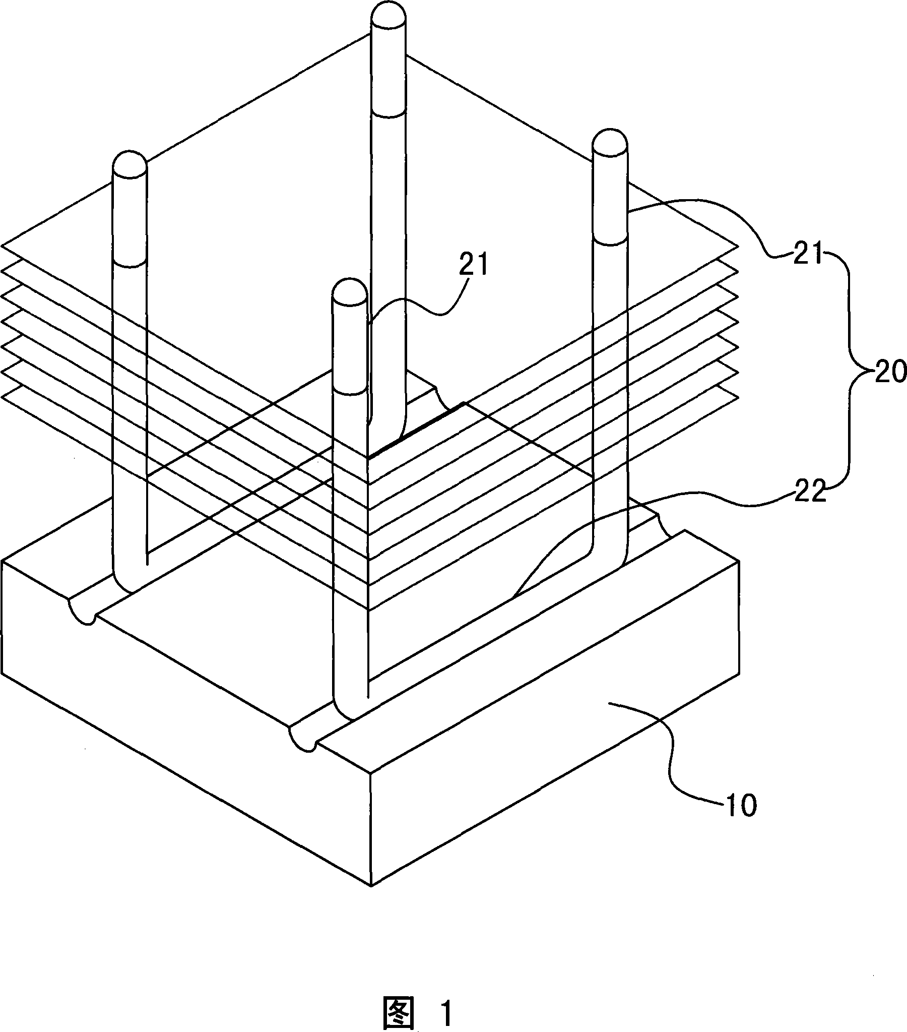
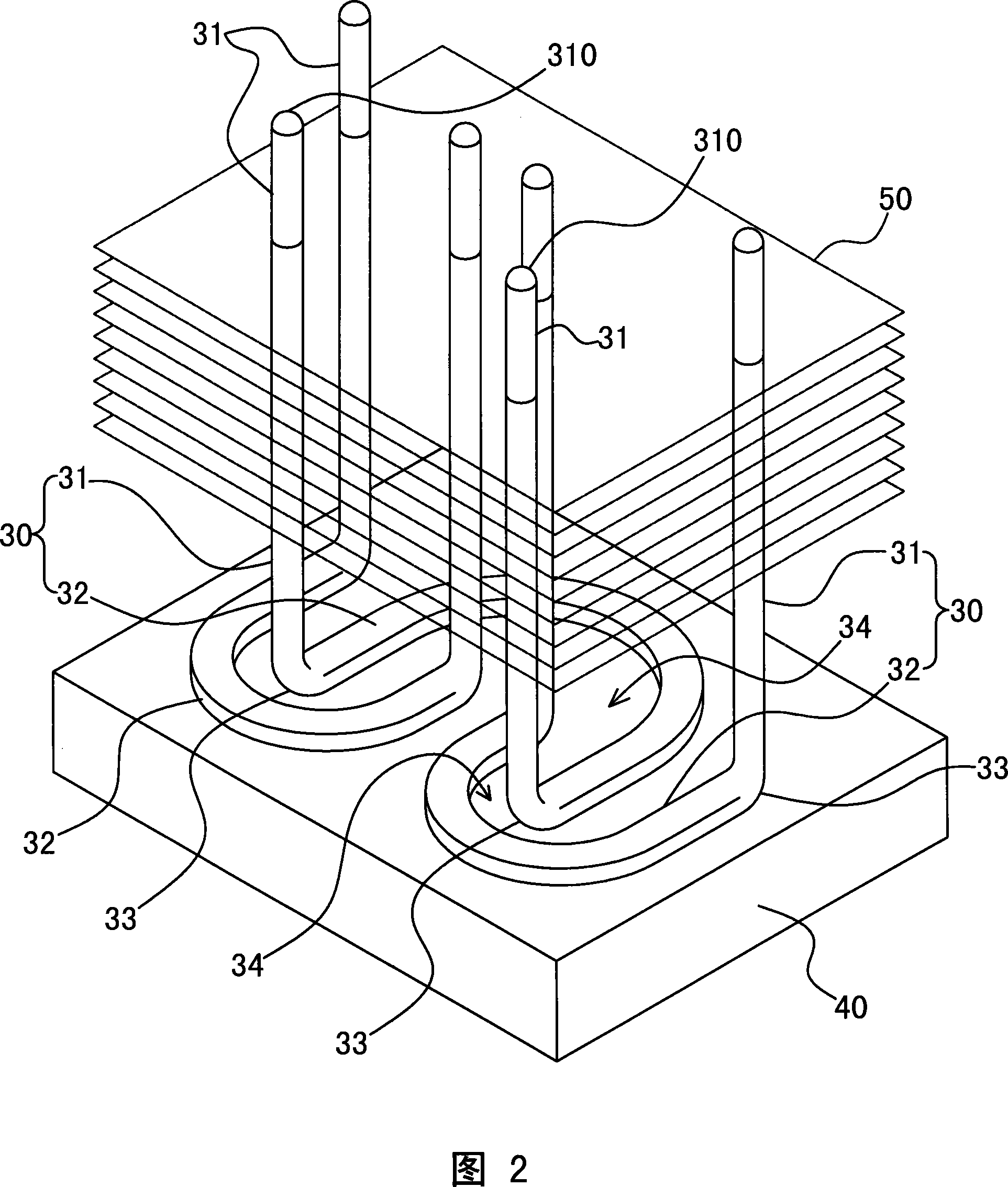
[0025] As shown in Figures 1 to 3, it is a preferred embodiment of the heat pipe structure of the radiator of the present invention; more than 30 heat pipes are arranged at intervals on a heat conduction base 40, and include two vertically upwardly protruding heat dissipation sections 31 , and the heat-receiving section 32 between the bottom ends of the two heat-dissipating sections 31, the heat-receiving section 32 rests on the heat-conducting base 40, and the junction of the heat-receiving section 32 and the two heat-dissipating sections 31 forms two turning parts 33, and the The heat dissipation section 31 is also provided with a predetermined number of heat dissipation fins 50;

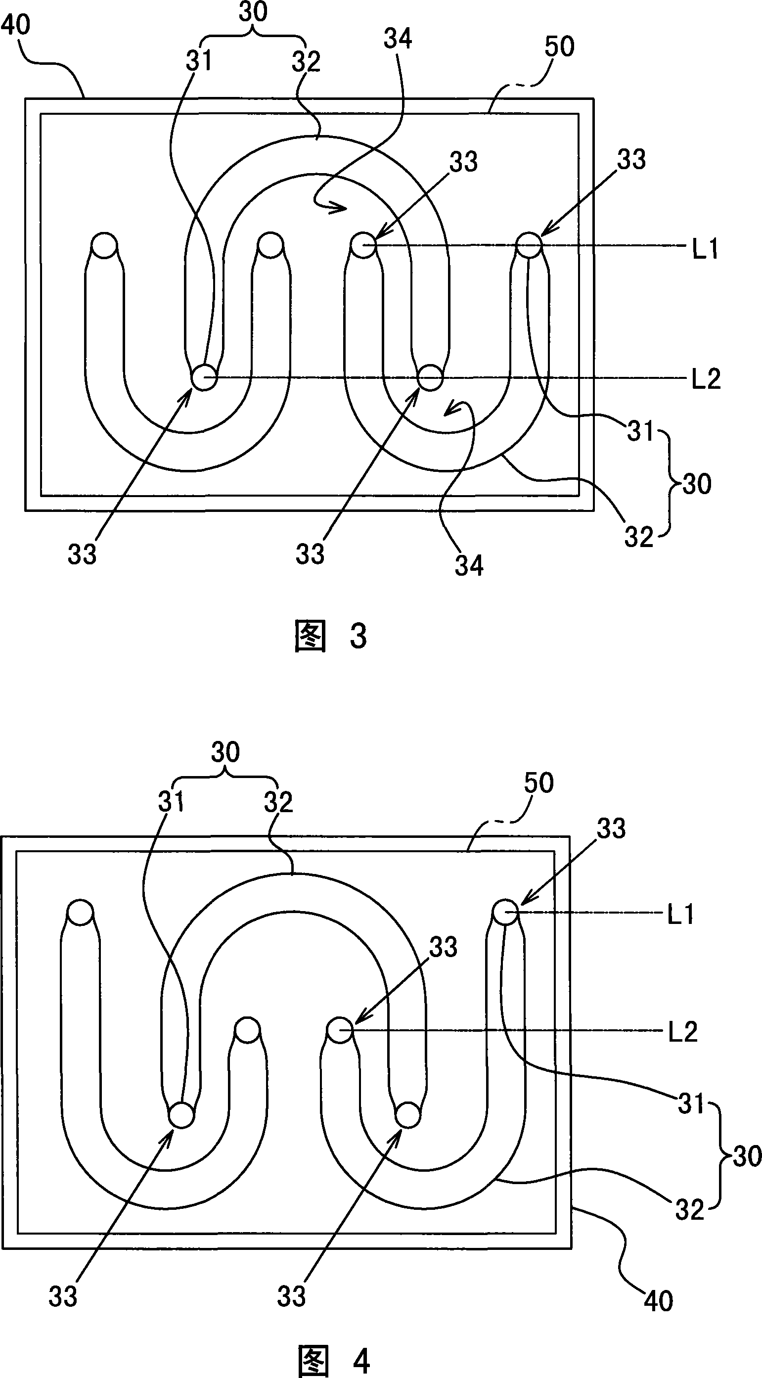
[0026] The features of the present invention include: the heating section 32 is arranged in a curved shape to form a concave space 34, and the heating sections 32 of the adjacent heat pipes 30 are in a relative dislocation relationship, that is, the heating of a heat pipe 30 The turning portion 33...


PUM


Abstract

A heat tube structure of a heat dissipater is disclosed, which includes two vertically extended heat dissipating sections, and a heat receiving section positioned between bottom ends of the two heat dissipating sections, wherein the heat receiving section is against a heat guide base seat, and connecting part of the heat receiving section and the two heat dissipating sections form a bending part. A relative better embodiment is mainly characterized in that the heat receiving section is set into a bending state, and heat receiving sections of adjacent heat tubes form relative version distribution, i.e. heat receiving section bending part of one heat tube is aligned to a concave space of another heat tube. Therefore, a largest heat receiving area can be obtained with a smallest heat tube assembling volume to realize practical improvement such as greatly improved heat dissipating function and reduced manufacture cost, thus achieving higher industrial economic benefits.

Description

technical field [0001] The invention relates to a radiator, in particular to an innovative design of its heat pipe structure. Background technique [0002] The heat sink referred to in the present invention is mainly composed of a heat conduction base on which a certain number of heat pipes are assembled, and fins can be assembled on the heat pipes to improve its heat dissipation effect. [0003] The existing structural form of the heat sink is shown in Figure 1, and each group of heat pipes 20 assembled on the heat conduction base 10 is in the shape of a ㄩ and forms two vertically protruding heat dissipation sections 21, and is located on the two sides. The straight tubular heating section 22 between the bottom ends of the cooling section 21 is arranged in a parallel and spaced state between the groups of heat pipes 20; the disadvantage is that this existing structure still has the following problems in actual use: [0004] Since the heating section 22 of the heat pipe 20 ...

Claims


Application Information

Patent Timeline
IPC IPC(8): H05K7/20H01L23/427
Inventor 饶振奇何信威黄子欣林于金
Owner SUZHOU FORCECON ELECTRIC
Why Eureka
Try Eureka