Device for preventing suspension area from breaking while taper piece filling liquid and drawing deep forming and forming method

A liquid-filled deep-drawing, suspended area technology, applied in forming tools, metal processing equipment, manufacturing tools, etc., can solve the problems of affecting the uniformity of the wall thickness of the parts, unable to realize the forming of the parts, and limit the size of the back pressure, and save the process. , Improve the forming limit, the effect of good shape stability

Inactive Publication Date: 2008-03-26
HARBIN INST OF TECH
View PDF0 Cites 28 Cited by
  • Summary
  • Abstract
  • Description
  • Claims
  • Application Information

AI Technical Summary

Problems solved by technology

[0003] In order to solve the problem of existing forming technology for conical parts with large height-to-diameter ratio and large cone angle, the liquid-filled deep drawing using a rigid blank holder will form a large suspended area during the forming process. Blank-holding force, the deep-drawing punch is drawn downward at a certain speed, and the liquid-filled deep-drawing is performed under the action of the back pressure in the liquid chamber (concave die), and is affected by the bulging and rupture factors in the suspended area. The size of the back pressure is limited, and it is still impossible to form parts with deep or large cone angles in one process. Multi-pass forming increases costs, prolongs the processing cycle, and the accumulation of multi-pass forming affects the uniformity of the part wall thickness. Provided is a device and forming method for preventing the breakage of the suspended area during the liquid-filled deep drawing of the conical part. The specific technical solution to solve the above problems is as follows:

Method used


Image

  • Device for preventing suspension area from breaking while taper piece filling liquid and drawing deep forming and forming method

Examples


specific Embodiment approach 1

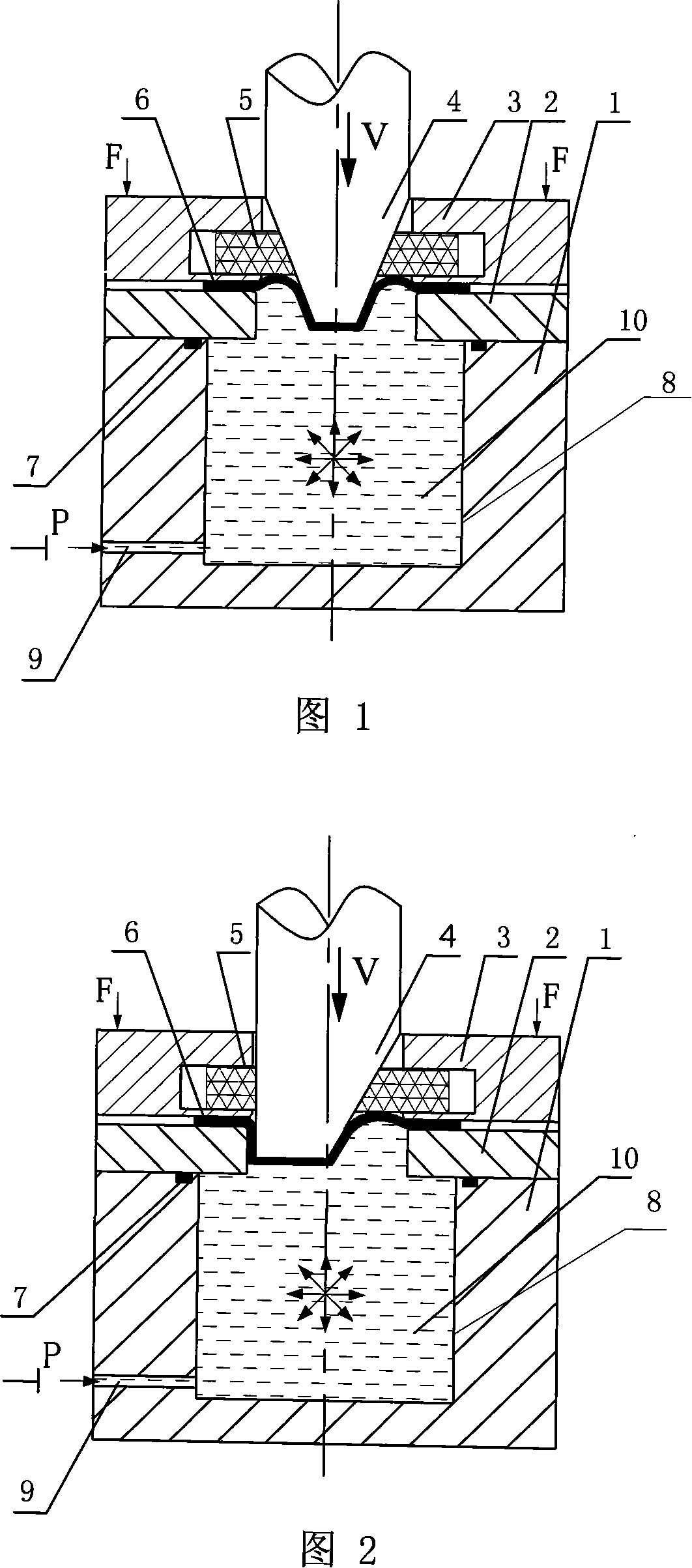
[0013] Specific implementation manner 1: This implementation manner is described in conjunction with FIG. 1 . This embodiment is composed of a fluid medium cavity 1, a die 2, a rigid blank holder 3, a punch 4 and a flexible support ring 5. The die 2 is arranged above the fluid medium cavity 1, and the lower plane of the die 2 is in contact with the The upper plane of the fluid medium cavity 1 is fixedly connected, the rigid blank holder 3 is arranged above the die 2, the inner ring of the rigid blank holder 3 has a groove, the flexible support ring 5 is arranged in the groove, and the flexible support ring 5 Urethane rubber material is used, and the plate blank 6 is placed between the rigid blank holder 3 and the die 2. There is a medium cavity 8 at the center of the upper surface of the fluid medium cavity 1, and the lower left side of the fluid medium cavity 1 is provided with A liquid injection hole 9 communicated with the medium chamber 8, and the liquid injection hole 9 c...

specific Embodiment approach 2

[0015] Specific Embodiment 2: This embodiment will be described in conjunction with FIG. 1 . Both the die 2 and the flexible support ring 5 in this embodiment are provided with inner holes for the punch 4 to pass through, and the maximum outer diameter of the punch 4 is smaller than the inner diameters of the rigid binder ring 3 and the die 2 . Ensure that the up and down movement of the punch 4 is deep drawn.

specific Embodiment approach 3

[0016] Specific Embodiment Three: This embodiment will be described in conjunction with FIG. 1 . The size difference between the inner diameter of the concave die 2 and the maximum outer diameter of the male die 4 in this embodiment is greater than the thickness of the formed plate blank 6 . When the plate blank 6 is pressed into the die 2, it will not break.


PUM


Abstract

The present invention relates to a conical component forming device capable of preventing floating zone from being broken when the conical component is formed by adopting liquid-charging and drawing process and its forming method. Said conical component forming device is characterized by that its rigid edge-pressing ring is set over a concave die, in said rigid edge-pressing ring interior a recessed groove is cut, a flexible supporting ring is placed in the recessed groove interior, said concave die is placed on the fluid medium cavity, and its liquid-injecting hole is connected with its hydraulic system. Its forming method includes the following steps; (1), making the liquid-injecting hole on the cavity body be communicated with the hydraulic system; (2), placing a plate blank on the concave die; (3), making the rigid edge-pressing ring be moved downwards and apply edge-pressing force; and (4), making convex die be downwards moved until the plate blank is drawn into the concave die interior with the convex die so as to obtain a formed conical component.

Description

technical field [0001] The invention relates to a device and a forming method for rupturing a suspended area of ​​a conical part through liquid-filled deep drawing. Background technique [0002] In the sheet metal forming process, for the sheet metal parts whose shape and size are consistent with the punch and the height-to-diameter ratio is greater than 1, it is difficult to form in one time by ordinary drawing. At present, fluid is usually used as a force transmission medium to assist forming processing. The principle is to make the sheet close to the punch under the action of fluid back pressure, and the back pressure enhances the friction effect between the blank and the punch, forming a beneficial friction force, which can offset the punch. The partial tensile stress of the blank at the rounded corner improves the bearing capacity of the deformed blank, thereby avoiding the rupture of the material at the rounded corner of the punch and realizing the forming of the sheet...

Claims


Application Information

Patent Timeline
Patent Type & Authority Applications(China)
IPC IPC(8): B21D26/02B21D37/10B21D26/021B21D26/031
Inventor 苑世剑徐永超
Owner HARBIN INST OF TECH
Why Eureka
Try Eureka