Solar energy flat glass house novel structure

A solar panel and glass house technology, applied to lighting and heating equipment, drying, furnace types, etc., can solve the problems of many consumables, low luminous flux, and high cost, and achieve high luminous flux, safe consumables, and low cost.

Inactive Publication Date: 2010-09-01
黄金伦
View PDF9 Cites 0 Cited by
  • Summary
  • Abstract
  • Description
  • Claims
  • Application Information

AI Technical Summary

Problems solved by technology

[0003] The purpose of the present invention is to provide a new structure of solar flat glass house, which solves the problems of many consumables, high cost and low luminous flux existing in the prior art

Method used


Image

  • Solar energy flat glass house novel structure
  • Solar energy flat glass house novel structure
  • Solar energy flat glass house novel structure

Examples


Embodiment Construction

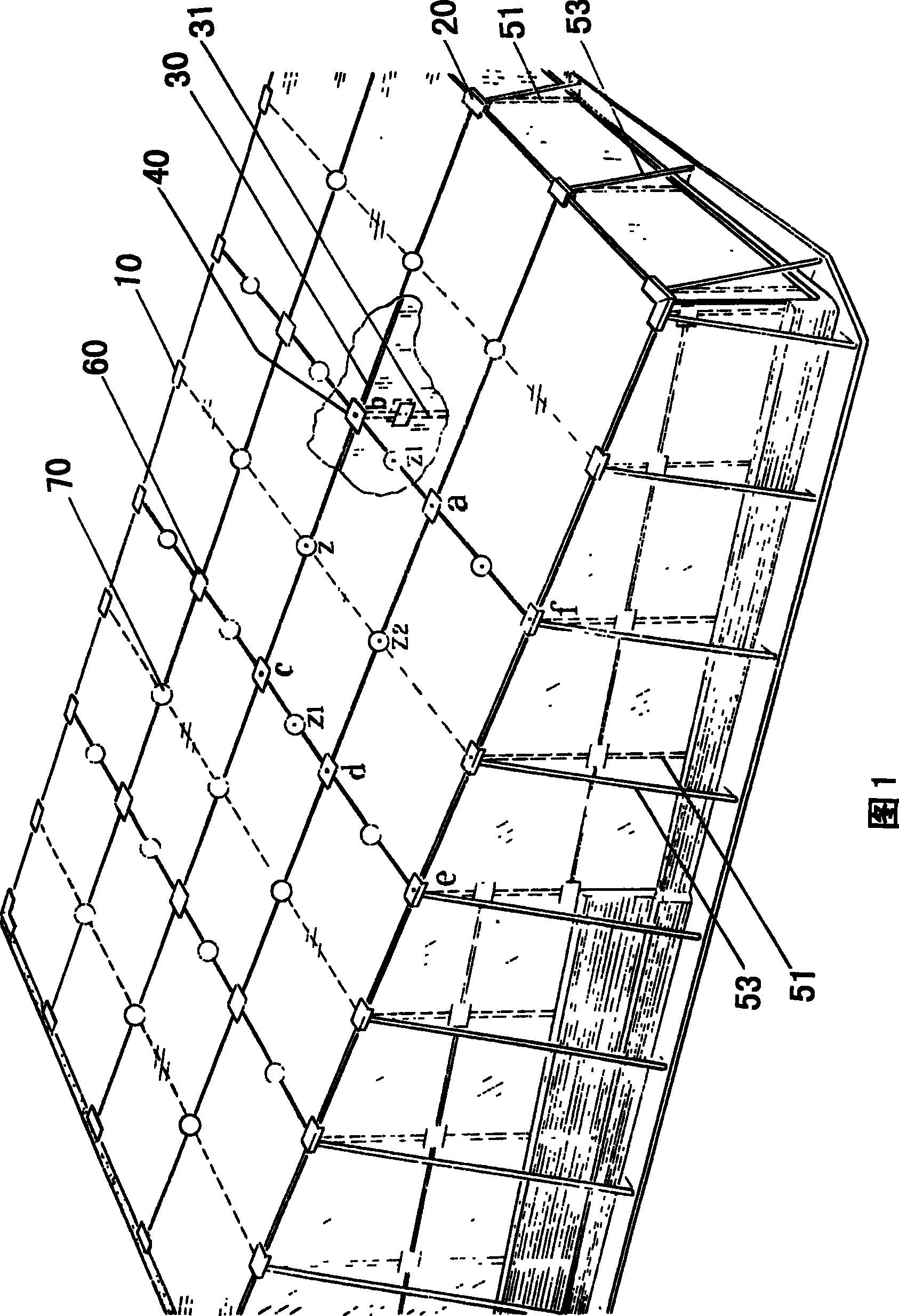
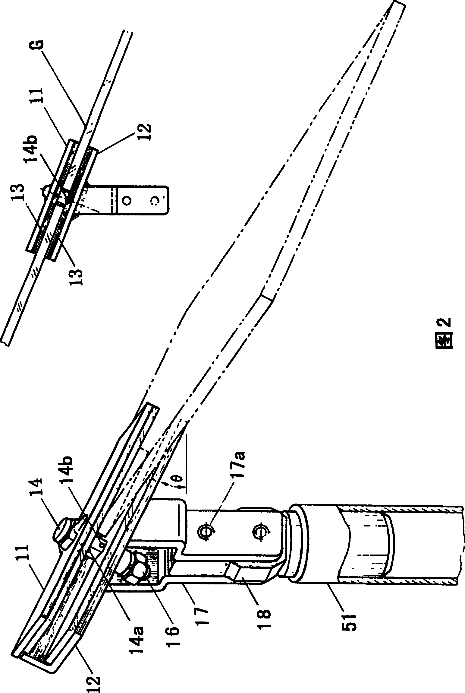
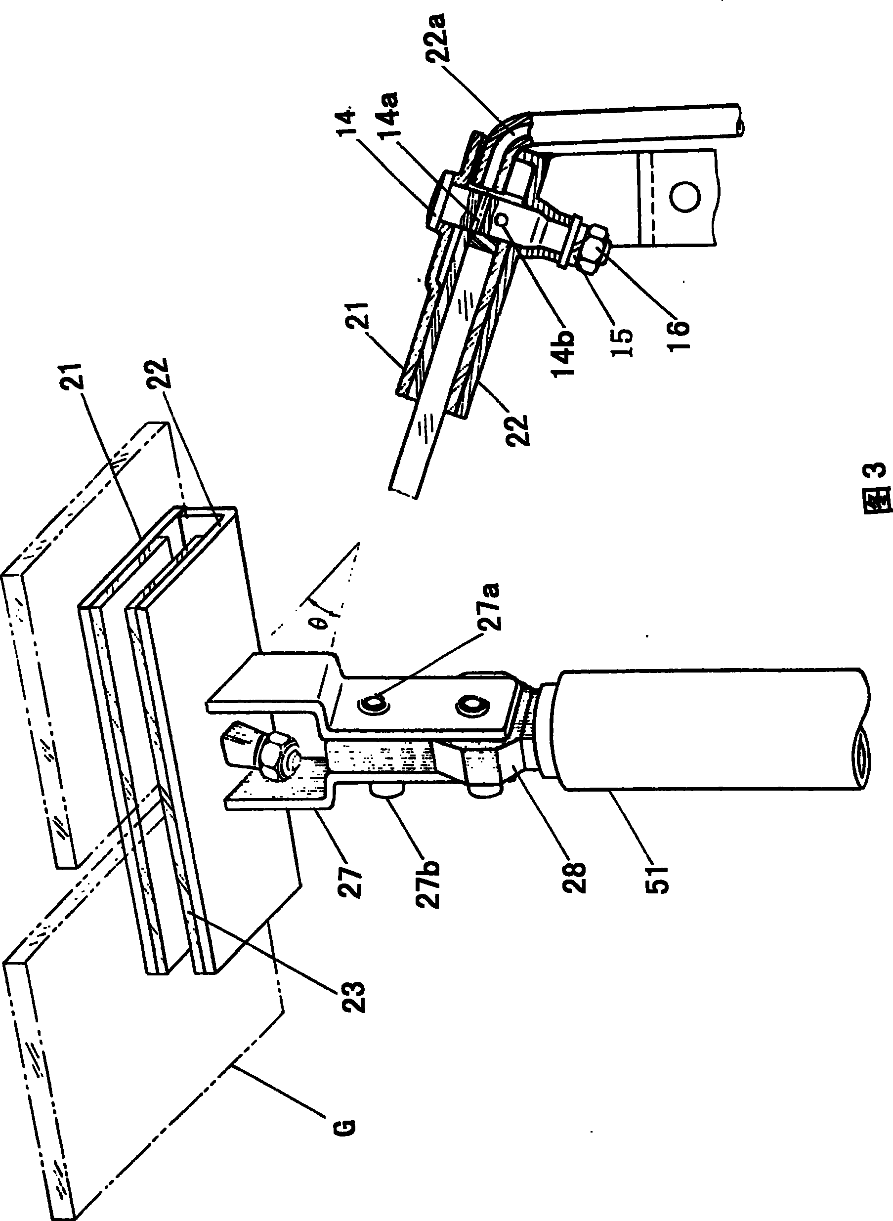
[0016] The features of the present invention are: 1. figure 1 The southeast and west three sides are all glass walls, and the north is a reinforced concrete partition wall (the middle partition is insulation material). The periphery of these four walls is evenly distributed with a tripod 50 welded by steel pipes, and its riser 51 (right-angled side) In the wall, the inclined pipe 53 (hypotenuse) is obliquely braced outside the wall, and the short right-angled side is horizontally embedded in the ground silicon base; Aluminum-zinc anti-corrosion) tensioned, criss-crossed steel wires form the entire roof slope. Four kinds of room surface clips are installed on the top of each tripod 50 with screws; On the steel wire, there are bolts with horizontal holes in the string, and then clamp the upper and lower clips with bolts (rubber gaskets are lined between the clip and the glass), and at the same time clamp each adjacent piece of glass and fix it with the tensioned steel wire , J...


PUM


Abstract

This invention is a solar energy plate glass house new structure. It has no beam, purlin and rafter. The luminous flux is high. The east, south and west faces of this house are all double layer middle septate glass wall. The north face is reinforced concrete sandwich wall. Steel pipe tripods are evenly distributed outside of the surrounding wall. They are transversely buried in the floor at the position of the stand pipe (right edge) of wall, oblique pipe (oblique edge) outside the wall and the short right angle edge. High strength steel wires (aluminum and zinc plated) are tensioned between the east-west tripod and south-north tripod. The crisscross steel wires form the oblique face of the whole roof. The steel wire formed panes are the position for assembling glasses. The tensioned steel wires in the gap between each glass are covered with bolt. The bolt has transverse hole and clips upper and lower clamping pieced firmly. Thus, the adjacent glasses are clipped. The glasses and steel wires form the roof together. The gaps between glasses are filled with glue. The bolt and tensioned steel wires are fixed in the gap by glue.

Description

technical field [0001] The invention belongs to the technical field of solar energy utilization and drying, and relates to a new structure of a solar flat glass house. Background technique [0002] The north-south longitudinal direction of the solar flat glass house in the prior art is very shallow, and it cannot form an updraft with a high temperature and a certain speed, so the evaporation efficiency is very low, so it is often used to strengthen the evaporation by blowing the material layer upwards in the room , which shows that the utility of the solar glass house is very small. In addition, even if a larger glass house is used, in order to support the glass roof and wind force, beams, wipers, rafters and columns must be used, which greatly increases man-hours and consumes materials. What's worse is that the luminous flux of the glass house is partially blocked. Contents of the invention [0003] The purpose of the present invention is to provide a new structure of a ...

Claims


Application Information

Patent Timeline
Patent Type & Authority Patents(China)
IPC IPC(8): F26B9/02F26B3/28
Inventor 黄金伦
Owner 黄金伦
Why Eureka
Try Eureka