

Polluted water or ground surface water source heat pump flow passage type heat transfer system
A surface water source heat pump and heat exchange system technology, applied in the field of heat exchange systems, can solve the problems of high initial investment, poor operation effect, and large floor space
- Summary
- Abstract
- Description
- Claims
- Application Information
AI Technical Summary
Problems solved by technology
Method used
Image

Examples
specific Embodiment approach 1
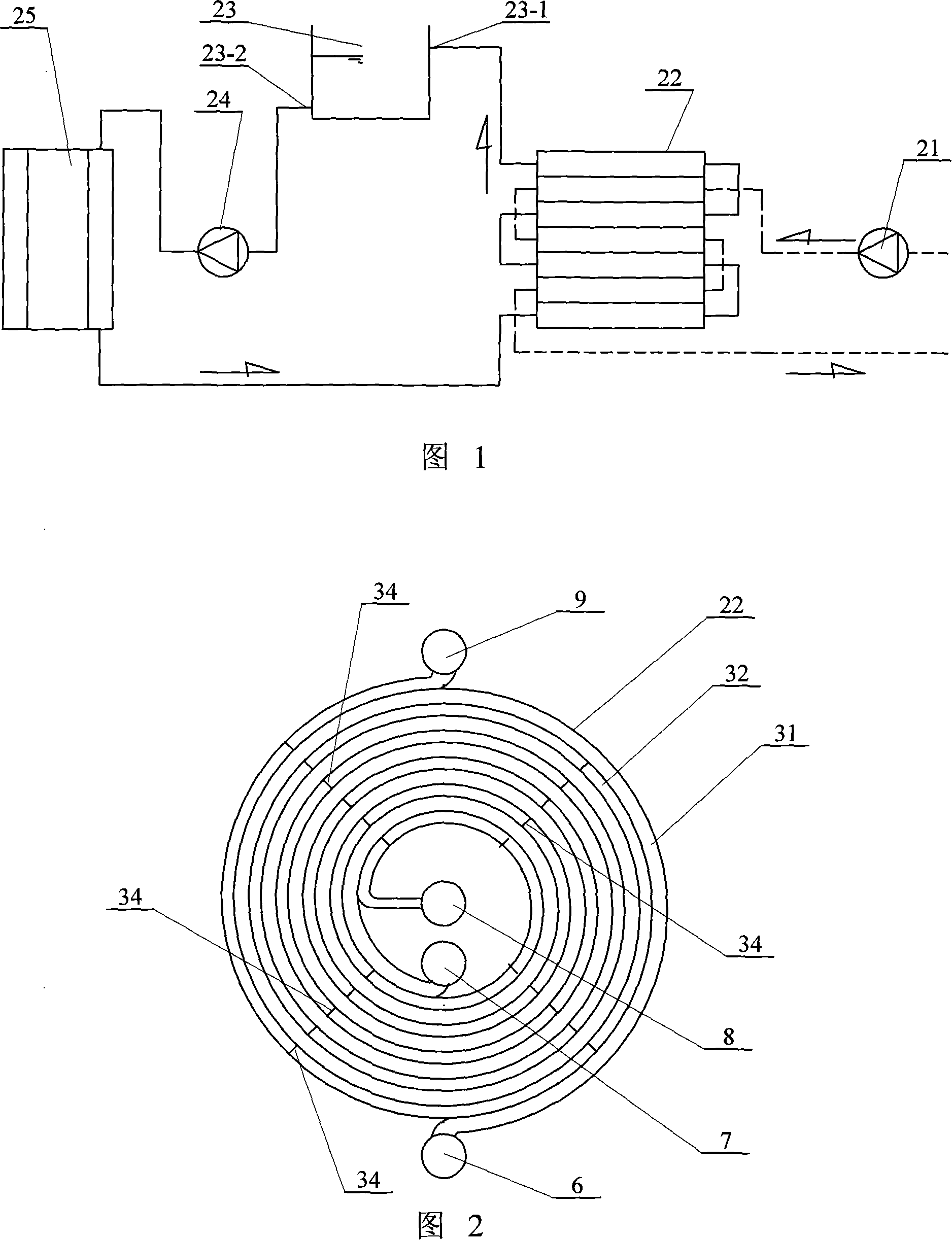
[0005] Specific embodiment one: (see Fig. 1) this embodiment is made up of sewage or surface water pump 21, channel type heat exchange device 22, pressure relief device 23, heat exchange medium pump 24 and heat pump unit 25, sewage or surface water pump 21 The outlet is connected with the sewage or surface water inlet of the flow channel heat exchange device 22, the sewage or surface water outlet of the flow channel heat exchange device 22 is connected with the water source of the sewage or surface water, and the flow channel heat exchange device 22 The heat medium outlet is connected to the inlet of the pressure relief device 23, the outlet of the pressure relief device 23 is connected to the inlet of the heat exchange medium pump 24, the outlet of the heat exchange medium pump 24 is connected to the inlet of the heat pump unit 25, and the heat pump unit 25 The outlet communicates with the inlet of the heat exchange medium of the channel heat exchange device 22 .
specific Embodiment approach 2
[0006] Specific embodiment two: (see Fig. 2) the flow channel type heat exchange device 22 of this embodiment is made up of spiral plate single flow channel and pull column 34, and the sewage or surface water flow channel 31 and heat exchange formed by the spiral plate single flow channel The medium flow channels 32 are arranged alternately. The two ends of the heat exchange medium flow channels 32 are respectively provided with a heat exchange medium inlet 8 and a heat exchange medium outlet 9. The two ends of the sewage or surface water flow channel 31 are respectively provided with a sewage or surface water inlet 6 and Sewage or surface water outlet 7, heat exchange medium inlet 8 and sewage or surface water outlet 7 are all arranged on the center side of the spiral plate, and tie columns 34 are fixed between the inner walls of both sides of the heat exchange medium flow channel 32 . In this embodiment, there is no pull column in the sewage or surface water flow channel, the...
specific Embodiment approach 3
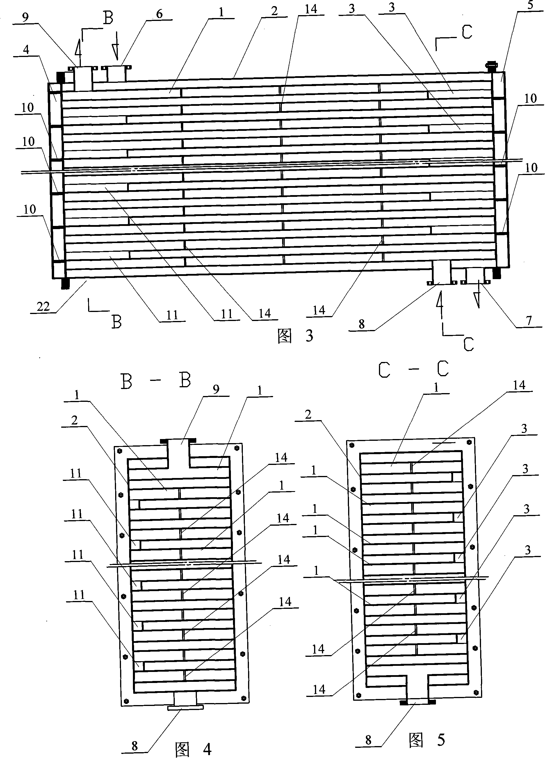
[0007] Specific embodiment 3: (see Fig. 3-Fig. 5) the channel type heat exchange device 22 of this embodiment adopts a flat plate structure, and the right cavity 3 and the left head 4 are connected by the heat exchange splint 1, the outer shell 2, and the splint , right head 5, sewage or surface water inlet 6, sewage or surface water outlet 7, heat exchange medium inlet 8, heat exchange medium outlet 9, head partition 10, splint connecting left cavity 11 and tie bars 14, The heat exchange splint 1 is fixed in the outer casing 2 from top to bottom, and the two ends of the tie bars 14 are respectively fixedly connected with the upper and lower inner walls of the heat exchange splint 1, odd and even numbers (the first heat exchange splint 1 and Between the second heat exchange splint 1, between the third heat exchange splint 1 and the fourth heat exchange splint 1...), the right end of the heat exchange splint 1 is connected with a splint connected to the right cavity 3, the even ...
PUM
 Abstract
Description
Claims
Application Information