

Multi-function motor
A multi-functional, rotor technology, applied in the shape/style/structure of magnetic circuit, magnetic circuit characterized by magnetic materials, and stationary parts of magnetic circuit, etc. High-level problems, to achieve the effect of simple structure, easy speed regulation and large torque
Inactive Publication Date: 2008-04-02
TIANJIN DEXIN ELECTRIC MACHINERY
View PDF0 Cites 0 Cited by
- Summary
- Abstract
- Description
- Claims
- Application Information
AI Technical Summary
Problems solved by technology
[0002] At present, among the existing motors, AC motors are difficult to adjust the speed, while DC motors have complex structures and high prices.
Method used
View moreImage
Smart ImageViewing Examples

Examples
Embodiment
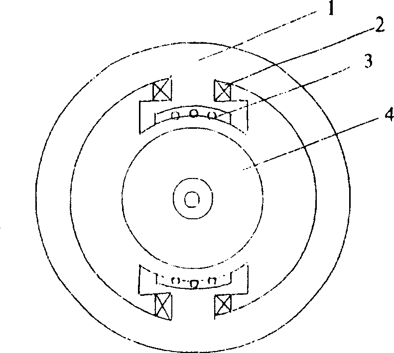
[0007] Example: A multifunctional motor. The motor is composed of a stator 1 and a rotor 4. The rotor is made of soft magnets. The stator is made of soft magnets or permanent magnets. It also includes a coil 3. The stator generates an excitation magnetic field to make the rotor Magnetization also produces a magnetic field. At this time, the rotor actually becomes a magnet with two poles. After the coil in the stator is supplied with current, it will interact with the rotor by electromagnetic force. Because the coil is fixed, the rotor has to rotate. If the core is continuous, the rotor will rotate continuously.
Login to View More PUM
 Abstract
A multifunctional motor comprises a stator and a rotor, wherein, the rotor is made of soft magnet, and the stator is made of soft magnet or permanent magnet, a coil is also included, a stator generates an exciting magnetic field to cause the rotor to be magnetized, and a magnetic field is generated, then the rotor actually becomes a magnet with two poles, after the coil in the stator is electrified, the stator and the rotor are provided with an interaction with electromagnetic force, as the coil is fixed, the rotor has to rotate, and as core bodies of the rotor are continuous, the rotor keeps on rotating. The invention has the advantages of simple structure, complete symmetry, reverse direction, easy speed regulation and high torque, moreover, a magnetic circuit of the stator is made of soft magnet, alternating current or direct current can be simultaneously used, if the rotor is driven to rotate by an external force, a generator is provided.
Description
Technical field [0001] The invention relates to a multifunctional motor. Background technique [0002] At present, it is difficult to adjust the speed of an AC motor among the existing motors, and a DC motor has a complicated structure and a high price. Summary of the invention [0003] The purpose of the present invention is to overcome the above-mentioned defects and provide a multifunctional motor. [0004] The technical solution of the present invention is: a multifunctional motor, which is characterized in that the motor is composed of a stator and a rotor. The rotor is made of soft magnets, and the stator is made of soft magnets or permanent magnets. It also includes a coil. Excite the magnetic field to magnetize the rotor and also generate a magnetic field. At this time, the rotor actually becomes a two-pole magnet. After the coil in the stator is supplied with current, it will interact with the rotor by electromagnetic force. Because the coil is fixed, the rotor has to R...
Claims
Login to View More Application Information
Patent Timeline
 IPC IPC(8): H02K1/02H02K1/14H02K1/17H02K1/22H02K3/04H02K3/18
Inventor马长富
OwnerTIANJIN DEXIN ELECTRIC MACHINERY