
Difference elliptic gear transplanting mechanism and uses thereof

The technology of oval gear and circular gear is applied in the field of high-efficiency sparse planting mechanism, which can solve the problems of reduced use range, unsuitable for rice planting with large plant spacing and sparse planting requirements, etc., and achieves the effects of reasonable structure, high transplanting efficiency and reliable work.

Inactive Publication Date: 2008-04-09
JIANGSU UNIV
View PDF1 Cites 5 Cited by
  • Summary
  • Abstract
  • Description
  • Claims
  • Application Information

AI Technical Summary

Problems solved by technology

But this mechanism is only suitable for the small seedling operation of rice seedlings in my country (that is, the plant spacing is adjustable from 120mm, 140mm, 160mm, 180mm to 200mm, and the seedling height is less than 200mm), and it is not suitable for planting multi-season rice in southern my country. That is, the seedling height exceeds 200mm) and the requirements of super rice seedlings (that is, the plant spacing is 300mm), and it is not suitable for the large plant spacing and sparse planting requirements of rice planting (ie, the plant spacing is adjustable from 200mm to 300mm), so its application range is greatly reduced.

Method used


Image

  • Difference elliptic gear transplanting mechanism and uses thereof
  • Difference elliptic gear transplanting mechanism and uses thereof

Examples


Embodiment Construction

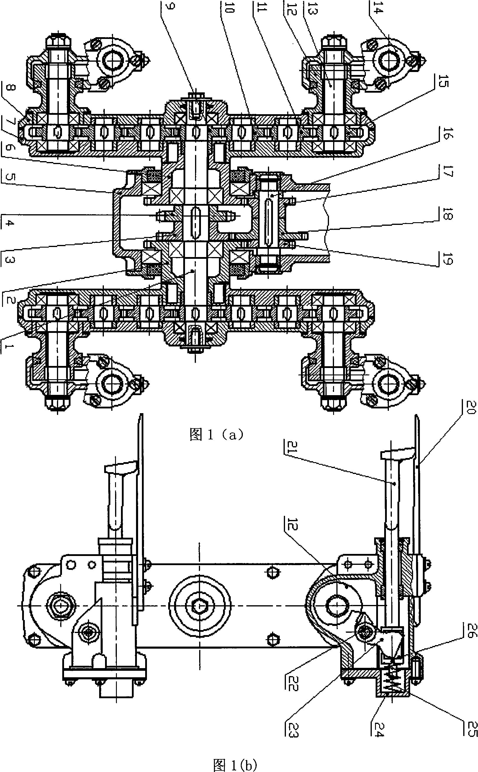
[0015] In Fig. 1, in the sprocket box (5), the power is transmitted to the driven sprocket (4) through the chain, and the driven sprocket (4) is consolidated with the driven sprocket shaft (1). Taking the left side structure of the whole device as an example, the upper and lower parts are symmetrical about the center line of the driven sprocket shaft (1). The other end of the driven sprocket shaft (1) is consolidated with the central oval gear (9), and the other end of the left sliding sleeve gear (6) is consolidated with the right casing (7) of the gear box. The power is transmitted in two routes: one transmission route is that the power is transmitted to the intermediate transition gear (18) meshed with the transition shaft (16) through the flange gear (3) installed on the same shaft as the driven sprocket (4) (transmission ratio is -1), drive the left and right transition gears (17,19) installed on both sides of intermediate transition gear (18) on the transition shaft (16)...


PUM


Abstract

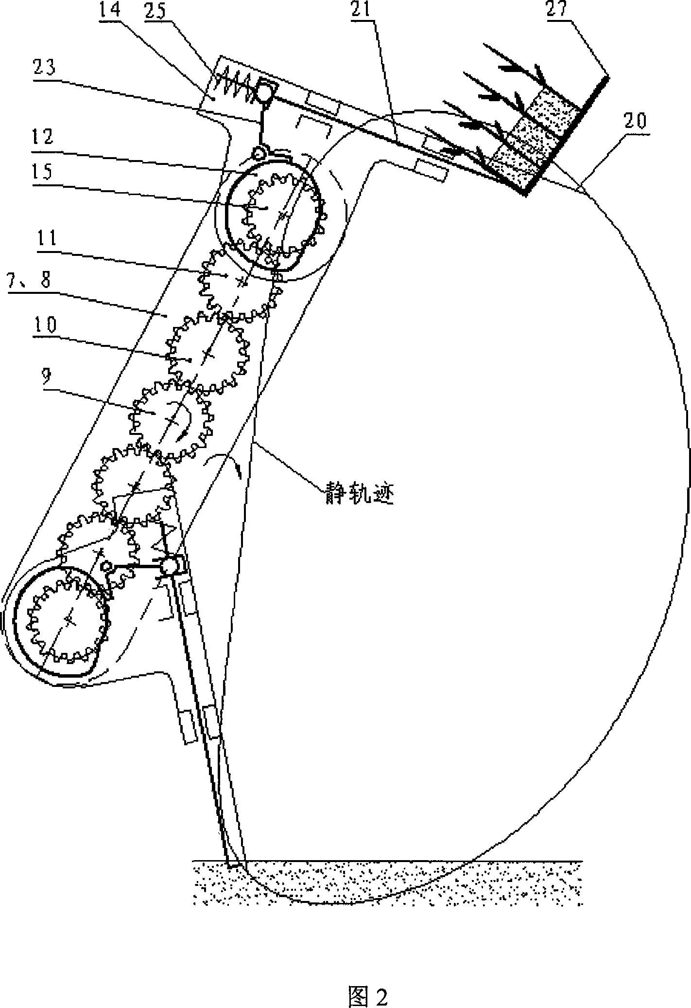
The invention provides a separating and transplanting mechanism and the purpose thereof in the differential ellipse gear system. The separating and transplanting mechanism consists of a chain wheel case (5) driven by medium differential speed, gear boxes (7, 8), and an insemination arm (14). The invention is characterized in that the drive power is inputted by a driven chain wheel (4) fixed on a driven chain wheel shaft (1) in the chain wheel case (5), and is transmitted to idler wheels (18) meshing with each other on a transition shaft (16) through a flange gear (3) to drive a left gearwheel and a right gearwheel (17, 19).And then the left gearwheel and the right gearwheel (17, 19) respectively mesh with a left and a right sliding-sleeve gearwheels (2, 6) on the driven chain wheel shaft (1) to drive the gear boxes (7, 8) on the left and the right large arms through the gearwheels (2, 6). At the same time, the driven chain wheel shaft (1) drives a central ellipse gearwheel (9), and then the drive power is transmitted to a planetary ellipse gear (15) to drive a consolidated planetary ellipse gear shaft (13), and then the consolidated inseminating arm (14) can be driven to move. The invention can be used in the sparse planting of the common rice seedlings with the distances from 200mm to 300mm, and the super rice seedlings transplanting work with the seedlings distances of 300mm.

Description

technical field [0001] The invention relates to a planting device for rice (comprising ordinary rice and super rice), in particular to a high-efficiency sparse planting mechanism that can complete seedling picking, seedling pushing, and seedling transplanting when rice seedlings are inserted by a ride-on machine. Background technique [0002] At present, the motor-driven rice transplanter sold in the domestic market has two types of planting mechanisms: one is a crank rocker type transplanting mechanism, and the other is an eccentric gear planetary system dividing mechanism used on Japanese high-speed rice transplanters. For the rice transplanters produced before 1985, no matter they were walking type rice transplanters or seated type rice transplanters, their splitting mechanism was a crank connecting rod type splitting mechanism. When the transplanting frequency exceeds 200 or more, the machine vibrates greatly, and is currently only widely used on walking-type rice transp...

Claims


Application Information

Patent Timeline
Patent Type & Authority Applications(China)
IPC IPC(8): A01C11/02A01C19/00F16H1/28
Inventor 尹建军
Owner JIANGSU UNIV
Learn More