A fluid pressure expanding type cutter chuck

A tool chuck and expansion technology, which is applied in the mechanical field, can solve the problems that cannot meet the requirements of high precision, and achieve the effect of providing surface quality, easy and convenient loading and unloading of tools, and improving service life

Inactive Publication Date: 2008-04-09
刘晓明
View PDF0 Cites 12 Cited by
  • Summary
  • Abstract
  • Description
  • Claims
  • Application Information

AI Technical Summary

Problems solved by technology

[0002] Existing hydraulic expansion tool chucks are widely used in manufacturing industries such as automobiles and machinery. They are suitable for machining centers and high-precision boring machines to hold drills, reamers, milling cutters, etc. The existing structure cannot meet the requirements of high precision.

Method used


Image

  • A fluid pressure expanding type cutter chuck

Examples


Embodiment 1

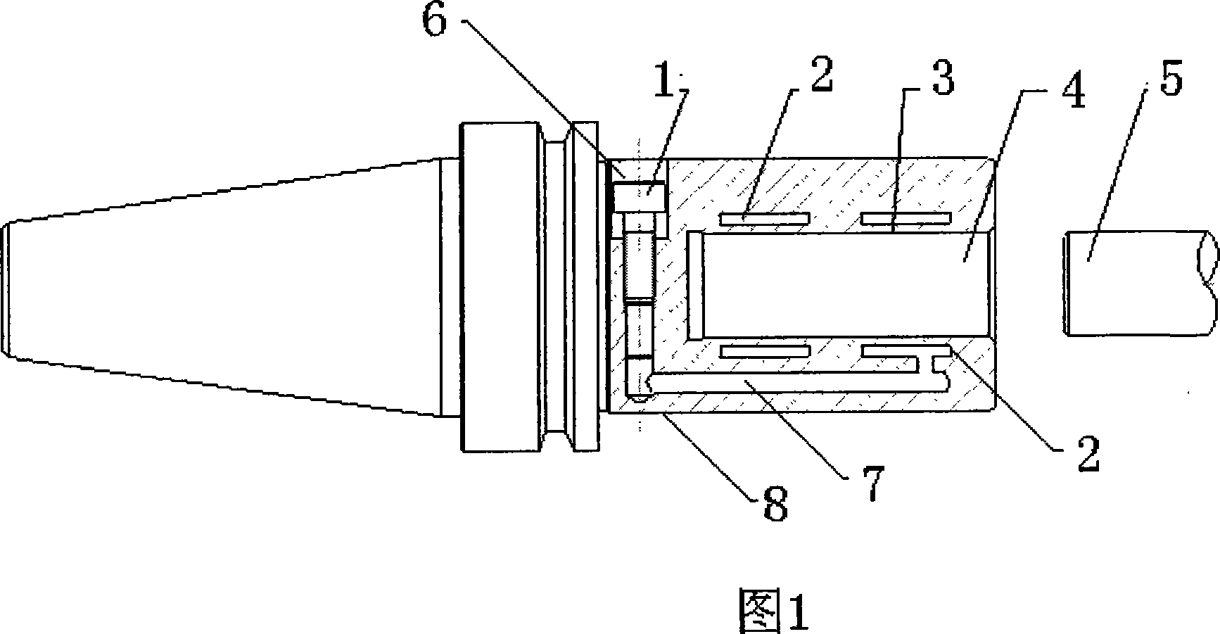
[0012] Embodiment 1: As shown in Figure 1,

[0013] The structure of the hydraulic expansion tool chuck is shown in the figure. There is an annular closed oil chamber 2 between the chuck body 8 and the expansion wall 3 of the clamping hole 4. The oil chamber 2 is filled with special hydraulic oil, which can The oil pressure is evenly transmitted to each part of the sealed oil chamber 2. There is a hole 6 on the chuck body 8, the hole 6 communicates with the oil chamber 2 through the oil passage 7, one end of the hole 6 is connected with a pressure bolt 1 to match, and the expansion wall of the clamping hole 4 is set through accurate calculation, It has good elasticity and can produce the required amount of expansion when the oil pressure reaches the set value. The tool 5 is put into the clamping hole 4, when the pressure bolt 1 is tightened with an inner hexagonal wrench to increase the oil pressure in the oil chamber, every part of the closed oil chamber 2 will receive the s...


PUM


Abstract

The invention relates to a hydraulic expansion type cutter clamping head. An annular sealed oil chamber is arranged between the expanding wall of the clamping head main body and a clamping head installation hole, wherein, the oil chamber is filled up with special hydraulic oil, the hydraulic oil is uniformly transmitted to each part of the sealed oil chamber, a hole is arranged on the clamping head main body, the hole is connected with the oil chamber though oil circuit, one end of the hole is connected and matched with a pressurization bolt, the expanding wall of the clamping head installation hole has well elasticity, and the required expanding quantity is produced when the oil pressure reaches a setting point. The inner wall of the oil chamber expands uniformly and symmetrically along the radial direction and the tightness value of the cutter is added; when the pressurization bolt is loosened, the oil pressure inside the oil chamber falls back, the inner wall of the clamping head installation hole returns to the original diameter affected by elastic-restoring force and loosen the cutter. The invention has the advantages that the clamping return precision is smaller than 0.3 micron; the repetitive clamping precision is smaller than 0.2 micron; the clamping force is smooth and reliable; high torque can be transmitted; the clamping system has full-sealed structure and no attrition, and wears well, and the handling of the cutter is simple and convenient.

Description

technical field [0001] The invention relates to a hydraulic expansion type tool chuck, which belongs to the field of machinery. Background technique [0002] Existing hydraulic expansion tool chucks are widely used in manufacturing industries such as automobiles and machinery, and are suitable for machining centers and high-precision boring machines to hold drills, reamers, milling cutters, etc. The existing structure cannot meet the requirements of high precision. Contents of the invention [0003] In order to overcome the shortcomings of the prior art structure, the present invention provides a hydraulic expansion tool holder. [0004] The technical solution adopted by the present invention to solve its technical problems is: [0005] A hydraulic expansion tool chuck, there is an annular closed oil chamber between the chuck body and the expansion wall of the clamping hole, the oil chamber is filled with special hydraulic oil, and the oil pressure is evenly transmitted t...

Claims


Application Information

Patent Timeline
Patent Type & Authority Applications(China)
IPC IPC(8): B23B31/30
Inventor 刘晓明
Owner 刘晓明
Why Eureka
Try Eureka