Marker for photo-etching machine aligning and aligning using the same

A technology for alignment marks and lithography machines, applied in the field of lithography machines, can solve the problems of unreliable provision of the highest alignment accuracy, inability to use high-order signals, and low power

Active Publication Date: 2008-04-09
SHANGHAI MICRO ELECTRONICS EQUIP (GRP) CO LTD
View PDF4 Cites 46 Cited by
  • Summary
  • Abstract
  • Description
  • Claims
  • Application Information

AI Technical Summary

Problems solved by technology

The advantage of this scheme is that it can achieve automatic capture and high alignment accuracy, but the disadvantage is that it requires a special wedge adjustment device and complicated adjustment. In addition, the high-order signals in the diffracted light are weak, while this method is Higher alignment accuracy is achieved by relying on high-order signals. In practice, as the power of the reflected signal (especially the high-order signal) of the mark (especially the silicon wafer mark) is too low, the high-order signal cannot actually be used. Therefore, it cannot reliably provide the highest alignment accuracy

Method used


Image

  • Marker for photo-etching machine aligning and aligning using the same
  • Marker for photo-etching machine aligning and aligning using the same
  • Marker for photo-etching machine aligning and aligning using the same

Examples


Embodiment Construction

[0045] The specific embodiments of the present invention will be further described below in conjunction with the accompanying drawings.

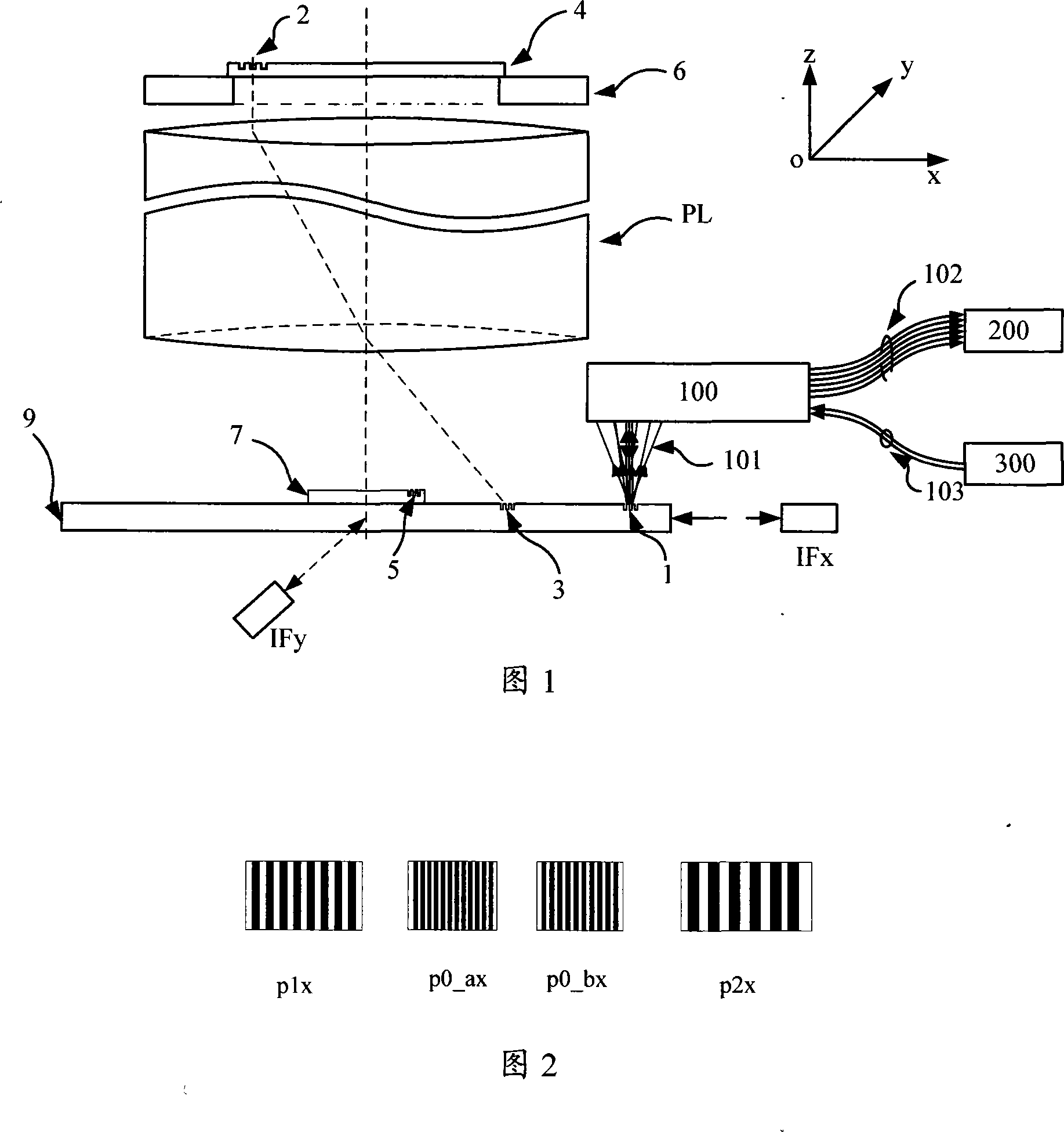
[0046] Fig. 1 shows an embodiment of the alignment system used in the prior art and the alignment method using four-period alignment marks of the present invention, the main structure of the photolithography machine includes: mask table 6, mask plate 4 , Projection objective lens PL, substrate table 9.

[0047] In the system used in the prior art, a lower-energy exposure radiation source or other non-exposure wavelength radiation source is used to irradiate the mask mark 2 on the mask plate 4 carried by the mask table 6, and the mask plate is projected through the projection objective lens PL. The reduced image of the mark 2 is projected onto the base table mark 3 as a set of reference marks on the base table 9, and the photoelectric signal conversion is performed by using the sensor that the base table mark 3 transmits thereunder, and the s...


PUM


Abstract

The present invention discloses an alignment mark and an alignment signal treatment method used for projection scanning lithography machine based on four-cycle phase grating. The method makes use of a marked coarse grating branch signal for the determination of capture range and position of the coarse alignment, and makes use a marked fine grating branch signal for the determination of the fine alignment position, thereby ensuring the obtainment of high-precision alignment position by only adopting diffraction optical signal of plus or minus 1 grade, improving the alignment efficiency and simplifying the alignment optical system.

Description

technical field [0001] The invention relates to lithography machine technology, in particular to the alignment technology of scanning projection lithography machine. Background technique [0002] Applying a step-and-scan projection lithography machine to complete the pattern transfer task of micromachining basically involves basic steps such as workpiece loading, alignment of the workpiece area to be processed with the mask, workpiece exposure, and workpiece unloading. In the case of multi-layer processing technology, the precise alignment of the workpiece area to be processed and the mask plate is the premise to ensure that the workpiece is correctly processed when the line width is continuously reduced. When the graphics are accurately projected to the workpiece area to be processed or a new When the accurate registration of the layer graphics is projected on the area of ​​the previously formed workpiece to be processed, the proper exposure of the current layer can realize...

Claims


Application Information

Patent Timeline
Patent Type & Authority Applications(China)
IPC IPC(8): G03F7/20G03F9/00
Inventor 李运锋韦学志徐荣伟陈勇辉周畅
Owner SHANGHAI MICRO ELECTRONICS EQUIP (GRP) CO LTD
Why Eureka
Try Eureka