Circuit arrangement, in particular phase-locked loop, as well as corresponding method

A technology of circuit layout and phase, applied in the field of phase-locked loop, can solve the problem of reducing PLL frequency, etc., and achieve the effect of easy work contraction

Inactive Publication Date: 2008-04-09
NXP BV
View PDF7 Cites 19 Cited by
  • Summary
  • Abstract
  • Description
  • Claims
  • Application Information

AI Technical Summary

Problems solved by technology

This reduces the f

Method used


Image

  • Circuit arrangement, in particular phase-locked loop, as well as corresponding method
  • Circuit arrangement, in particular phase-locked loop, as well as corresponding method
  • Circuit arrangement, in particular phase-locked loop, as well as corresponding method

Examples


Embodiment approach

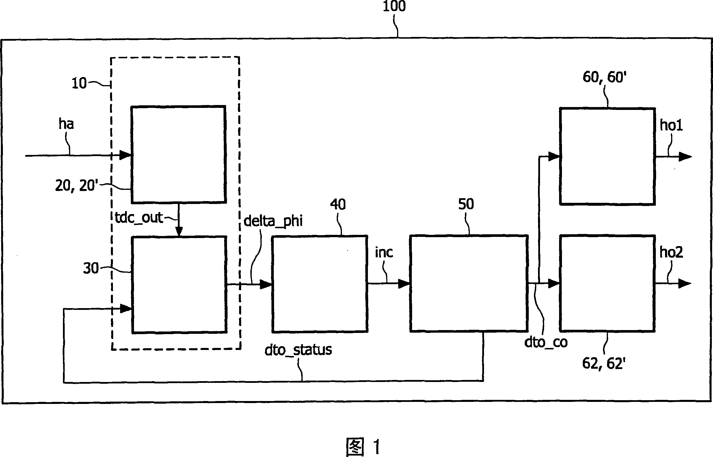
[0314] - time-to-digital converter 20 (see Figures 8, 9: first embodiment, without sample-and-hold stage) or 20' (see Figures 10, 11, 12: second embodiment, with sample-and-hold stage ss);

[0315] ---filter 40 (see Fig. 2: first embodiment, proportional (P) control is arranged) or 40 ' (see Fig. 3: second embodiment, proportional integral (PI) control is arranged);

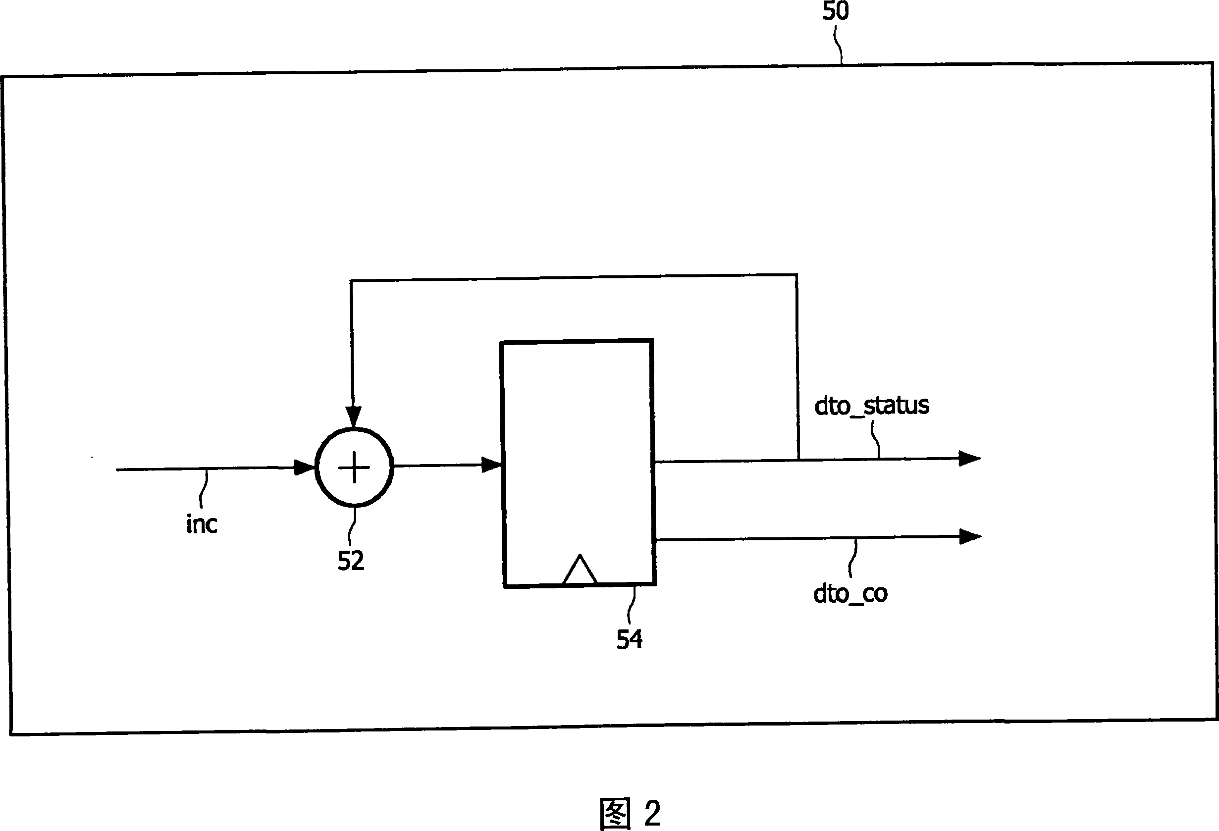
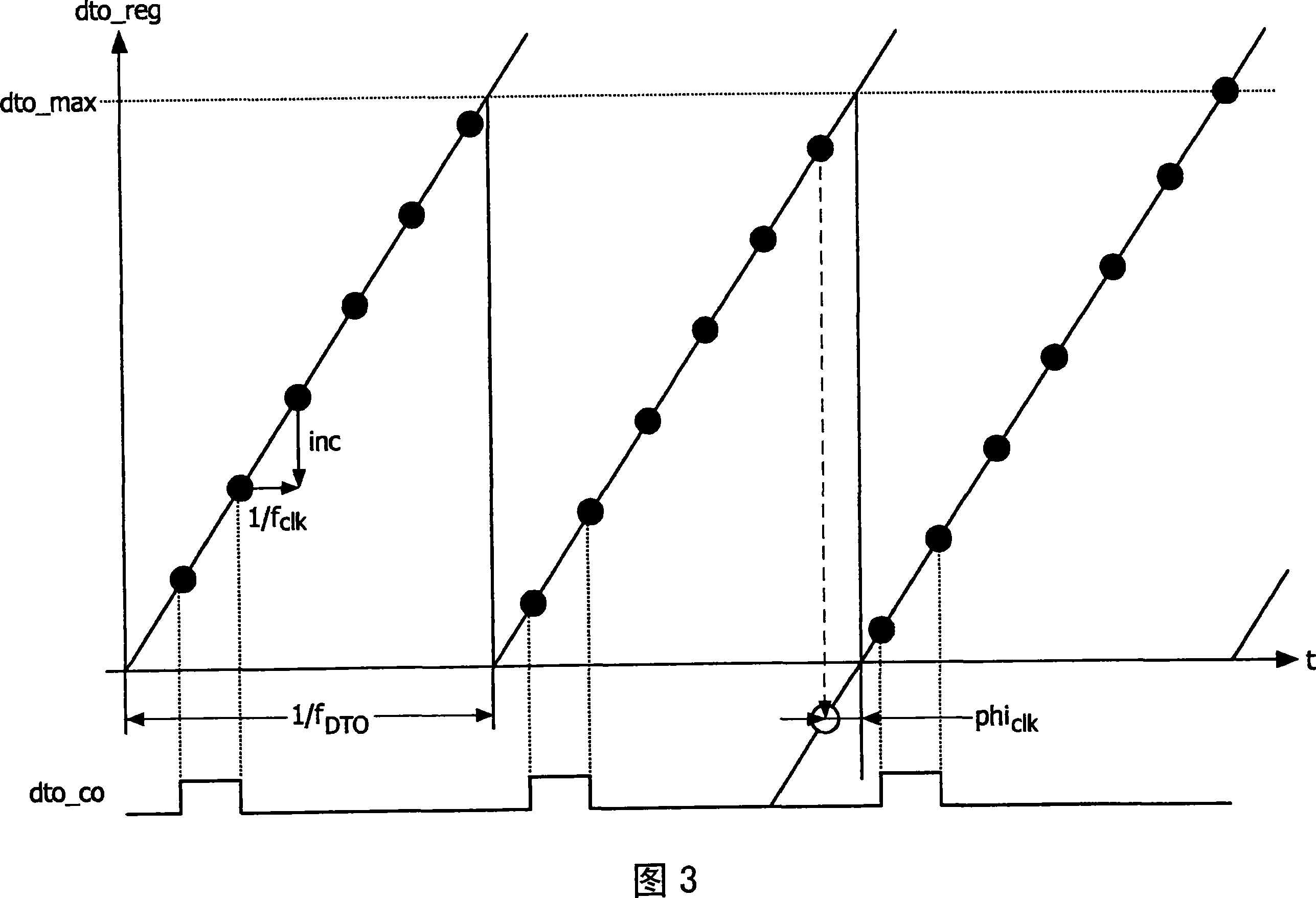
[0316] - Digital Ramp Oscillator or Discrete Time Oscillator 50 (see Figures 4, 5: first embodiment, no control of flyback value, maximum content or maximum value dto_max; see also Figure 20: no pipelining and Embodiment of adder unit split; FIG. 21 : embodiment with pipeline without adder unit split; FIG. 22 : embodiment without pipeline with split of adder units 502 and 504) or 50′ (see Figures 6, 7: Second embodiment with control of flyback value, maximum content or maximum value dto_max); and / or

[0317] --Digital-to-time converters 60, 62 (see Fig. 13, 14: first embodiment, without sample-and-hold stage) or...


PUM


Abstract

In order to further develop a circuit arrangement (100), in particular to a phase-locked loop for sub-clock or sub-pixel accurate phase-measurement and phase-generation, as well as a corresponding method in such way that no clock multiplier phase-locked loop is to be provided behind the time-to-digital converter and that neither an analog delay line nor a signal divider unit is to be provided between the digital ramp oscillator or discrete time oscillator and the digital-to-time converter, wherein less analog circuitry is susceptible for noise and for ground bounce in the digital environment, it is proposed to provide at least one phase measurement unit (10); - at least one loop filter unit (40; 40') being provided with at least one output signal (delta-phi) of at least one phase detector unit (30); at least one digital ramp oscillator unit or discrete time oscillator unit (50; 50') being provided with at least one output signal, in particular with at least one increment (inc), of the loop filter unit (40; 40'), the status signal (dto-status) of at least one register unit (54; 54') of the digital ramp oscillator unit or discrete time oscillator unit (50; 50') being fed back as input signal to the phase detector unit (30); and at least one digital-to-time converter unit (60, 62; 60', 62') being provided with at least one output signal (dto-co) of the digital ramp oscillator unit or discrete time oscillator unit (50; 50') and generating at least one output signal (hoi, ho2).

Description

technical field [0001] The present invention relates to circuit arrangements, in particular to phase-locked loops and corresponding methods for phase measurement and phase generation with sub-clock or sub-pixel precision. Background technique [0002] In a digital circuit, a clock signal needs to be generated to trigger a digital core in an analog-to-digital converter (ADC) or a latch unit (FF) in a sample-and-hold gate, specifically a flip-flop. In many cases, it is sufficient to derive this clock from a crystal oscillator. [0003] In cases where the clock needs to have a specific frequency or phase relationship to the input signal, clock generation must be controlled. This is the field of application for frequency-locked loops (FLL), phase-locked loops (PLL) or delay-locked loops (DLL). [0004] This control loop approach can be implemented in the analog or digital domain. In the analog domain, the time constant of the loop cannot be too large because of noise, leakage...

Claims


Application Information

Patent Timeline
IPC IPC(8): H03L7/099H03L7/091
CPCH03L2207/50H03L7/093H03L7/0991
Inventor 乌里希·莫尔曼蒂莫·吉赛尔曼埃德温·舍佩恩登克弗兰克·勃兰特伦德特·阿尔贝图斯·迪克·范登布罗埃克
Owner NXP BV
Why Eureka
Try Eureka