High voltage DC transmission converter valve maximum transient test methods
A technology of high-voltage direct current transmission and test method, which is applied in circuit breaker testing, measurement of electricity, measurement of electrical variables, etc. The effect of favorable strategies, clear results, and simple and easy-to-implement methods
- Summary
- Abstract
- Description
- Claims
- Application Information
AI Technical Summary
Problems solved by technology
Method used
Image
Examples
Embodiment Construction
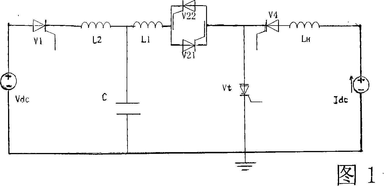
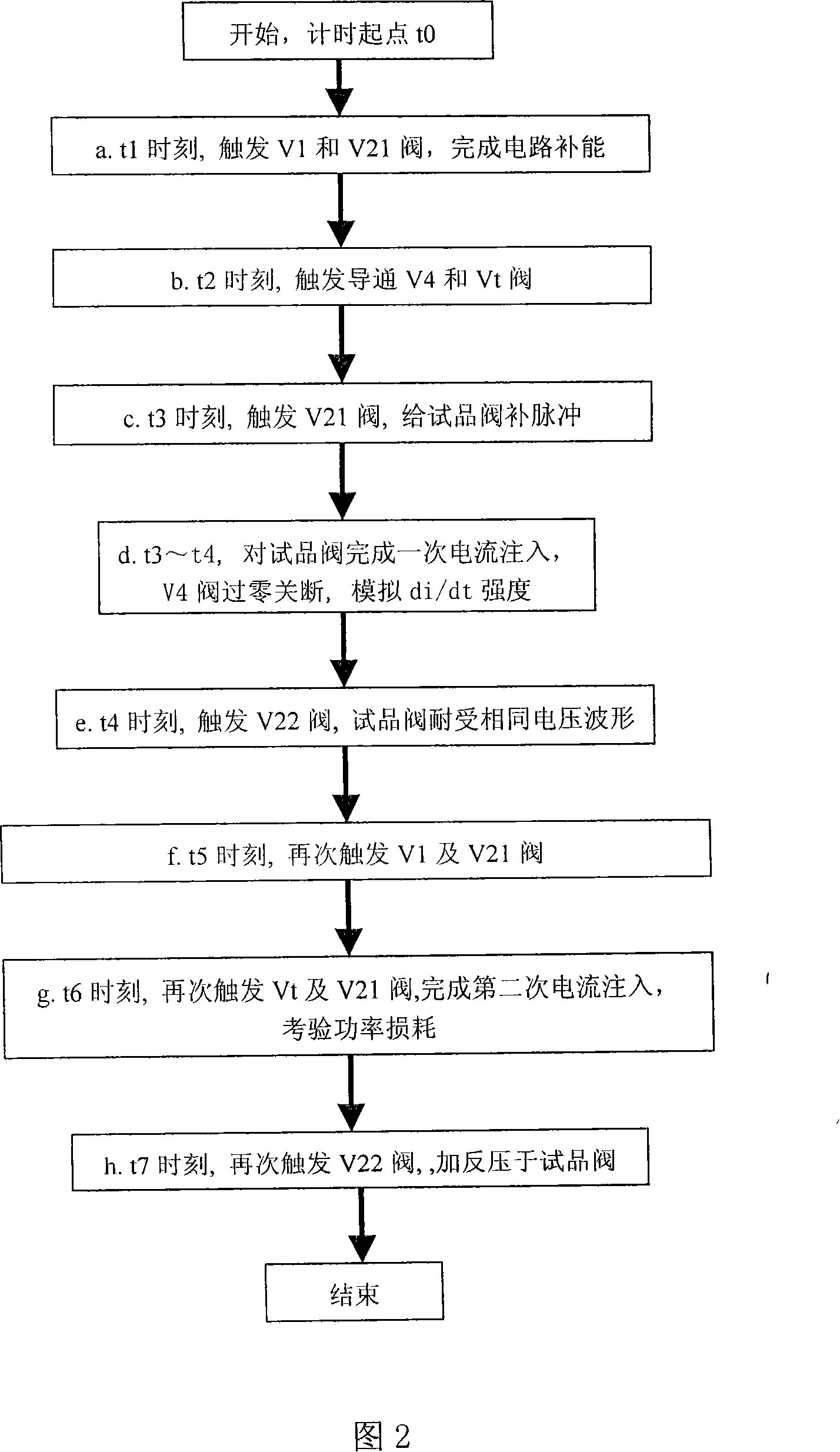
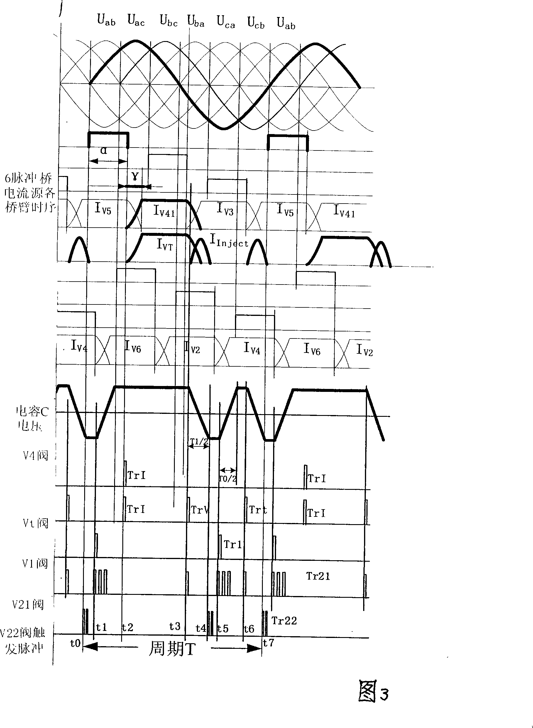
[0018] Referring to Fig. 1, it shows the schematic circuit diagram of the maximum transient state test of the HVDC converter valve. In the figure, the DC current source Idc is composed of 6 pulse bridges, V 1 , V 4 , V 21 , V 22 Respectively represent the auxiliary valve, V t Represents the sample valve, C represents the resonant capacitor bank, L 1 is the resonant reactor, L 2 To protect the reactor, L H is a large current reactor, V dc stands for a DC voltage source. The specific connection method is: the DC voltage source V of the high voltage circuit dc The anode output is connected to the voltage source auxiliary valve V 1 anode, V 1 The cathode of the protective reactor L is connected in series 2 After and resonant reactor L 1 One end of the resonant capacitor C is connected, the other end of the resonant capacitor C is connected to the cathode of the DC voltage source, and the other end of the resonant reactor is connected in series with an antiparallel reso...
PUM
 Abstract
Description
Claims
Application Information
 - R&D
- Intellectual Property
- Life Sciences
- Materials
- Tech Scout
- Unparalleled Data Quality
- Higher Quality Content
- 60% Fewer Hallucinations
Browse by: Latest US Patents, China's latest patents, Technical Efficacy Thesaurus, Application Domain, Technology Topic, Popular Technical Reports.
© 2025 PatSnap. All rights reserved.Legal|Privacy policy|Modern Slavery Act Transparency Statement|Sitemap|About US| Contact US: help@patsnap.com


