High voltage DC transmission converter valve three injection test methods

A high-voltage direct current transmission and test method technology, which is applied in the direction of circuit breaker testing, electricity measurement, and electric variable measurement, can solve problems such as the public report of the three-injection test method for high-voltage direct current transmission converter valves, and achieve protection strategies Favorable, simple and easy to implement test method, clear results

Active Publication Date: 2008-04-16
CHINA ELECTRIC POWER RES INST +1
View PDF0 Cites 5 Cited by
  • Summary
  • Abstract
  • Description
  • Claims
  • Application Information

AI Technical Summary

Problems solved by technology

[0003] At present, there are no similar public reports on the three-injection test method of HVDC converter valves at home and abroad.

Method used


Image

  • High voltage DC transmission converter valve three injection test methods
  • High voltage DC transmission converter valve three injection test methods
  • High voltage DC transmission converter valve three injection test methods

Examples


Embodiment Construction

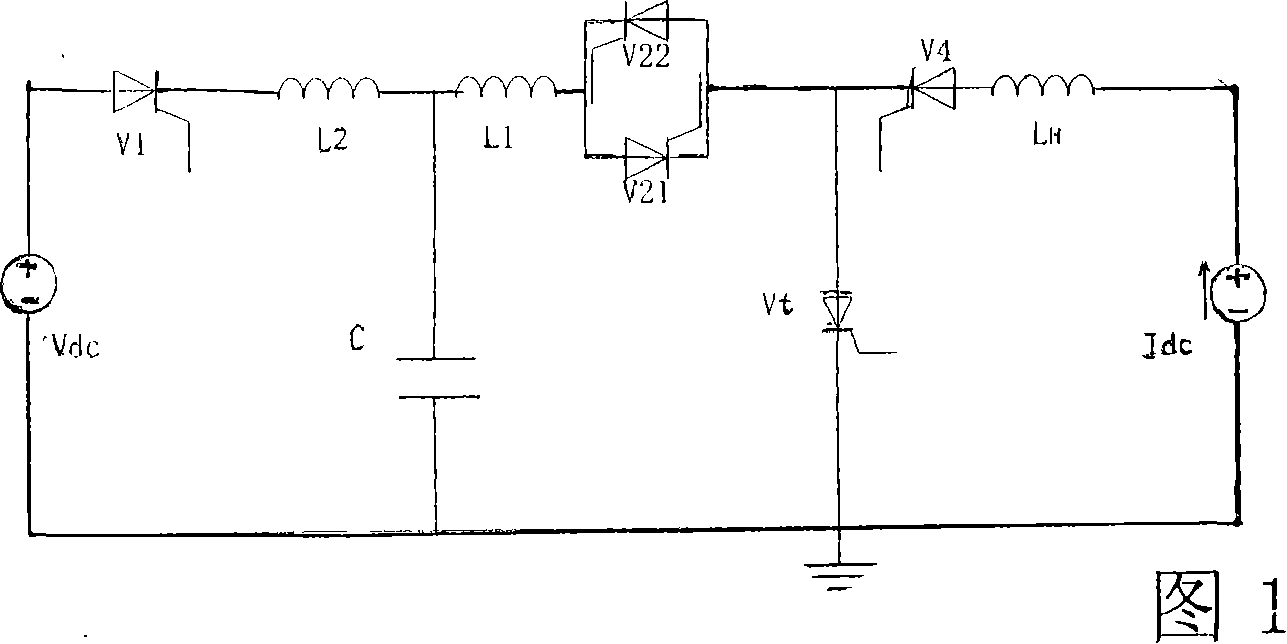
[0020] Referring to FIG. 1 , it shows the circuit diagram of the three-injection test principle of the HVDC converter valve. In the figure, the DC current source Idc consists of a 6-pulse bridge, V 1 , V 4 , V 21 , V 22 respectively represent the auxiliary valve, V t represents the test valve, C represents the resonant capacitor bank, L 1 is the resonant reactor, L 2 To protect the reactor, L H is a high current reactor, V dc Represents a DC voltage source. The specific connection method is: the DC voltage source V of the high-voltage circuit dc The anode output of the connected voltage source auxiliary valve V 1 the anode, V 1 The cathode of the protective reactor L2 is connected in series with the resonant reactor L 1 It is connected to one end of the resonant capacitor C, the other end of the resonant capacitor C is connected to the cathode of the DC voltage source, and the other end of the resonant reactor is connected in series with the anti-parallel resonant a...


PUM


Abstract

The invention discloses a method for a high voltage direct current valve three implantation test, belonging to the power electronic and power system field, wherein the synchronous voltage of the test is the input voltage of a big-current source; the working sequence of the test is determined by the synchronous signals; steps in a test cycle beginning at the time of t0 include: triggering service valves V1 and V21 to simulate the dv / dt intensity at the time of t1; triggering a test valve Vt and the service valve V21 to simulate the di / di intensity when the test valve is put into operation at the time of t2; triggering a valve V4 at the time of t3 which is also the time when a six-pulse bridge is at a triggering angle of alpha; triggering the service valve V1 at the time of t4; triggering the valve V21 and replenishing the test valve with pulse to conduct the test valve to simulate the di / dt intensity when the test valve is shut off at the time of t5; triggering a valve V22 at the time of t6; triggering the valves V1 and V22 again at the time of t7; triggering the test valve Vt and the service valve V21 again at the time of t8; and triggering the service valve V22 and applying counter pressure on the test valve at the time of t9. The adopted synchronous signals are commonly used; meanwhile, the method is easy to carry out with obvious results and meets the requirement of the operation of the high voltage direct current valve.

Description

technical field [0001] The invention belongs to the field of power electronics and power systems, and particularly relates to a three-injection test method for a converter valve of high-voltage direct current transmission. Background technique [0002] With the gradual popularization of HVDC technology in power systems, the reliability of its core component, the HVDC converter valve, has become the key to system security. The operation test, a process of strictly scientifically testing the performance of the valve in advance, is an important means to improve the reliability of the HVDC converter valve design and manufacturing level. At present, the synthetic test method is widely used in the world to carry out the operation test of the HVDC converter valve. The basic idea is to use two sets of power supply systems to provide high current and high voltage intensity for the thyristor valve respectively, thereby greatly reducing the capacity of each set of test power supplies ...

Claims


Application Information

Patent Timeline
Patent Type & Authority Applications(China)
IPC IPC(8): G01R31/00G01R31/333
Inventor 温家良查鲲鹏汤广福贺之渊杨晓楠
Owner CHINA ELECTRIC POWER RES INST
Why Eureka
Try Eureka