Method of implementing embedded device address installation by RS 485 bus competition
A technology of embedded devices and device addresses, applied in the bus network, data exchange through path configuration, etc., can solve the problems of high anti-interference, loss of versatility, unsuitable for application, etc., to improve the degree of intelligence and high reliability Effect
- Summary
- Abstract
- Description
- Claims
- Application Information
AI Technical Summary
Problems solved by technology
Method used
Image

Examples
Embodiment 1
[0058] A certain company has produced a certain type of embedded power system, which is widely used in various telecom equipment manufacturers and operators across the country. The power system consists of AC power distribution, DC power distribution, up to 10 rectifiers and a monitoring unit. Due to the requirement of power density and the pressure of cost, the rectifier does not have any human-computer interaction equipment except for an alarm indicator light and RS485 interface. Therefore, the monitoring unit needs to be connected to the 10 rectifiers through the RS485 bus, and the data and alarm information of each rectifier can be obtained by polling through a simple communication protocol, and the operating status of the rectifier can be controlled.
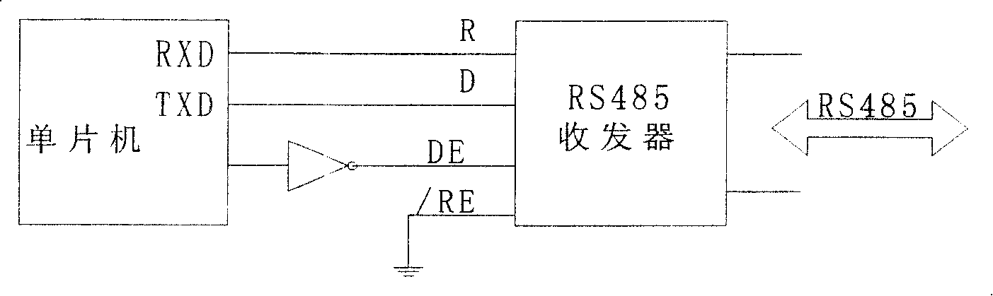
[0059] image 3 It is the hardware schematic diagram of the specific embodiment 1 of the present invention. As shown in the figure, due to the need for bus competition, the RS485 hardware control signal is slightly change...
PUM
 Abstract
Description
Claims
Application Information
PatSnap Eureka turns technology decisions into work you can execute. Powered by our Innovation Knowledge Graph, it runs expert workflows across engineering, life sciences, materials and intellectual property. Get your review-ready output in minutes.


