Apparatus and method for producing energy at a pulp mill

A technology in the pulp and paper industry, applied in the field of waste liquid recovery boilers, can solve problems such as superheater corrosion

Inactive Publication Date: 2008-04-16
ANDRITZ AG
View PDF2 Cites 10 Cited by
  • Summary
  • Abstract
  • Description
  • Claims
  • Application Information

AI Technical Summary

Problems solved by technology

Because the sulfur content of the bark is very low, the chlorine in the bark

Method used


Image

  • Apparatus and method for producing energy at a pulp mill

Examples


Embodiment Construction

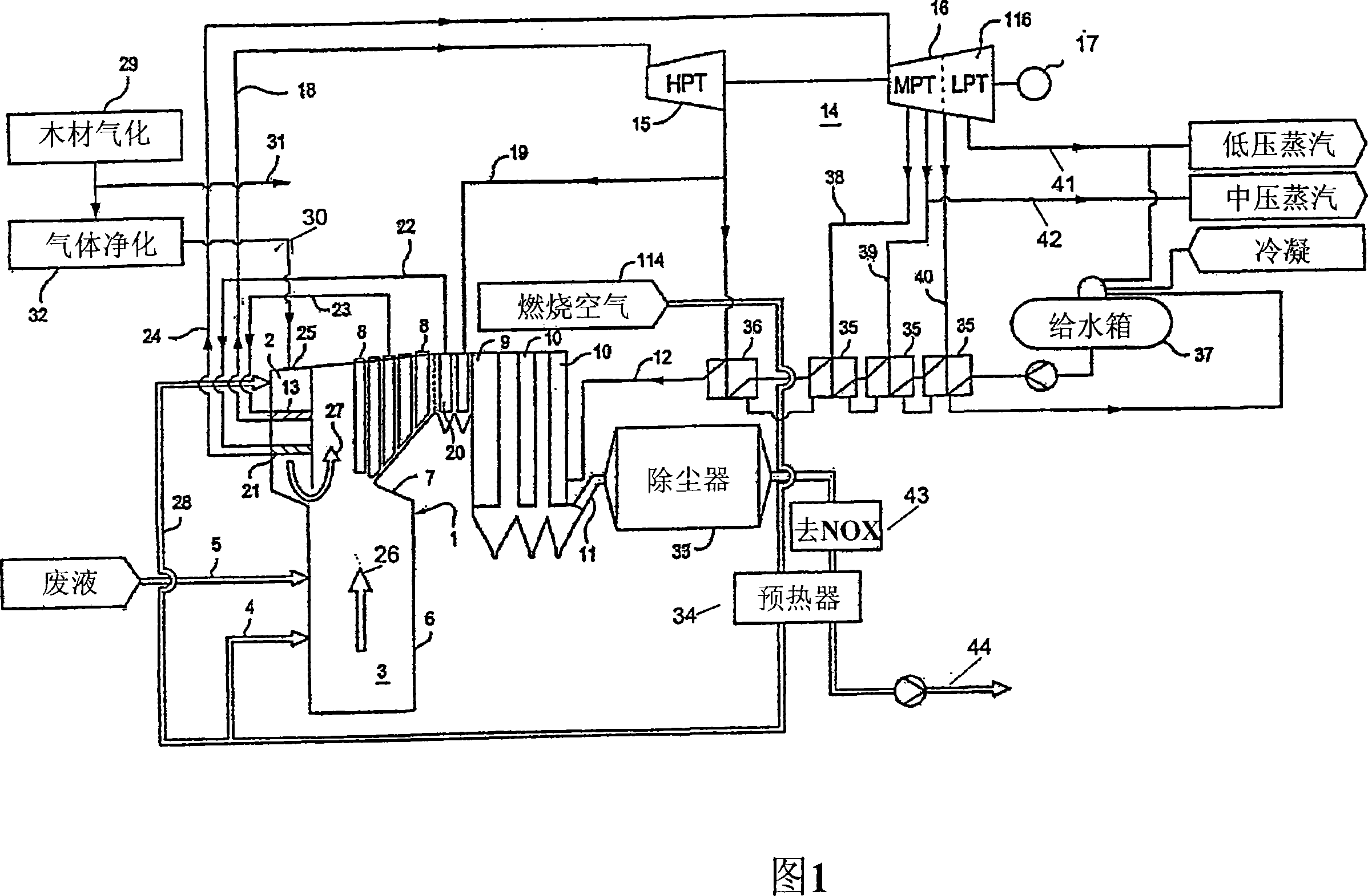
[0075] FIG. 1 shows a furnace 3 of a typical recovery boiler 1 , such as a kraft pulp recovery boiler for burning black liquor, which has a structure formed by water-cooled tube walls 6 . The water-steam mixture produced in this way is superheated by a conventional superheater 8 located partly in the "nose" hood above the furnace. The heat of the flue gases 26 produced during the combustion of the black liquor is recovered in the superheater 8 . Typically, boiler tube bundles 9 and economizers 10 act as post heating surfaces in the boiler. After the superheater, the flue gas is directed into the boiler tube bundle 9 and the economizer 10 .

[0076] The recovery boiler 1 comprises a cavity 2 which can be arranged close to the upper part of the boiler wall. The flue gas 26 produced by the furnace 3 of the recovery boiler flows upwards from the cavity 2 and through the inflow opening. Combustion air 4 is fed into the furnace to facilitate combustion, usually at several levels,...


PUM


Abstract

A spent liquor recovery boiler in the pulp and paper industry including a water/steam circulation system having superheaters, the circulation system connected to a steam turbine comprising a high-pressure part, and a furnace for burning spent liquor to produce flue gases, and including an upper portion through which the flue gases flow, wherein the steam/water circulation system of the recovery boiler is provided with a reheater for reheating steam from the high-pressure part of the turbine.

Description

technical field [0001] The present invention relates to a waste liquid recovery boiler, which includes a water / steam circulation system with a superheater and a reheater, and a furnace for burning waste liquid to generate hot flue gas. flow through the upper part. This water / steam cycle system is connected to a steam turbine consisting of a high-pressure stage and an intermediate-pressure stage. Superheating of live steam and reheating of steam are performed using arrangements that reduce corrosion. Background technique [0002] In chemical pulp mills, waste liquor (e.g. black liquor in kraft pulping) is recovered from spent liquor by burning the spent liquor alone or with other "waste" streams in a recovery boiler recovery of cooking chemicals. The combustion process is exothermic and the energy released is recovered to pressurize the superheated steam. In the steam turbine, the energy of the steam is recovered in the form of electrical energy and the steam at different...

Claims


Application Information

Patent Timeline
IPC IPC(8): D21C11/06D21C11/12F01K7/22
CPCY02E20/12F22B31/045F01K3/247F01K7/22D21C11/125D21C11/12
Inventor 卡里·萨维哈留约尔马·西莫宁奥利·阿尔帕拉赫蒂拉塞·科伊维斯托
Owner ANDRITZ AG
Why Eureka
Try Eureka