Particulate matter detection sensor
A particulate matter, detection sensor technology, applied in instruments, membrane filters, machines/engines, etc., can solve problems such as overpressure, fuel efficiency reduction, engine damage, etc., to eliminate ash deposition and suppress fuel efficiency decline.
- Summary
- Abstract
- Description
- Claims
- Application Information
AI Technical Summary
Problems solved by technology
Method used
Image
Examples
no. 1 approach
[0055] Figure 4 The configuration of the exhaust purification device according to the first embodiment of the present invention is shown.
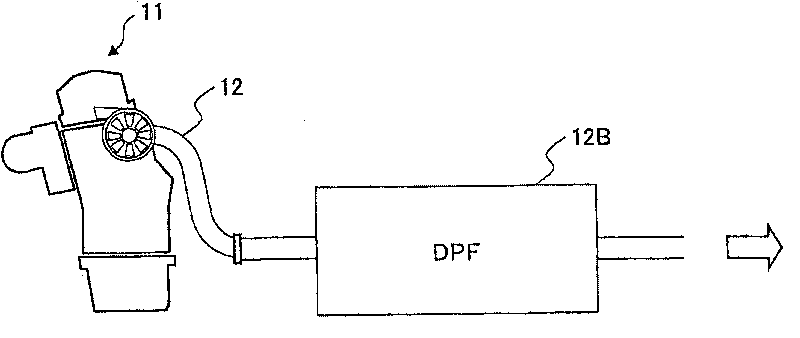
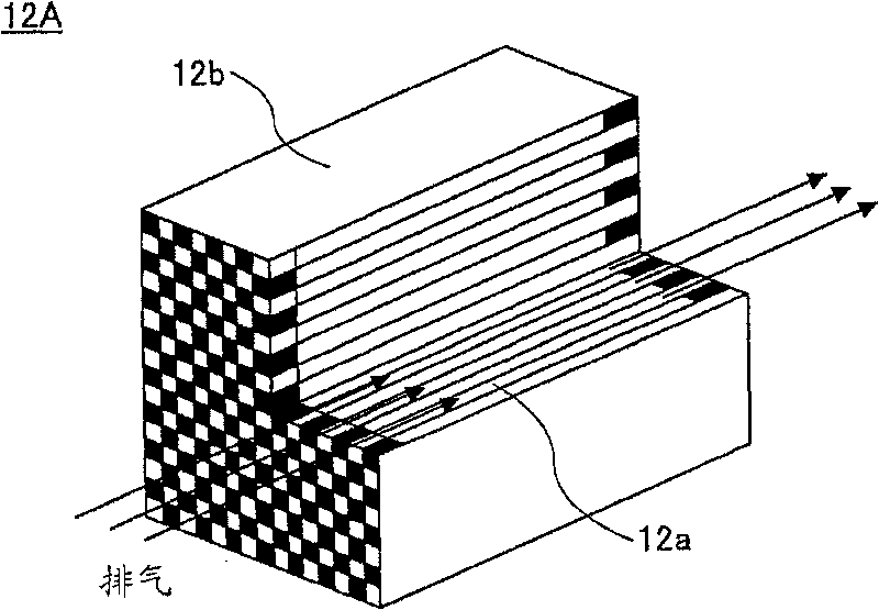
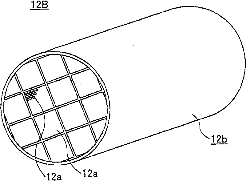
[0056] refer to Figure 4 , allowing exhaust gas from a diesel engine not shown to flow in via exhaust line 21 as previously referred to Figure 2A A similar primary diesel particulate filter (DPF) 22 as described, and as referenced Figure 2C and 2D As illustrated, a primary diesel particulate filter (DPF) 22 collects particulate matter in the exhaust.
[0057] Additionally, for Figure 4 Composition, from the upstream side of the main diesel particulate filter (DPF) 22, the auxiliary exhaust line 21A is branched from the exhaust line 21, and a volume smaller than the main diesel particulate filter (DPF) is set for the auxiliary exhaust line 21A ) of the secondary diesel particulate filter 22A. In addition, a differential pressure measuring portion 22B is provided for measuring the differential pressure ΔP caused between the inlet ...
no. 2 approach
[0097] Figure 8 shows the use according to a second embodiment of the invention Figure 4 A flow chart of the exhaust purification method of the exhaust purification device.
[0098] refer to Figure 8 , in step S1, the exhaust gas flow rate Q is detected by using the flow meter 24, and the differential pressure ΔP across the sub diesel particulate filter 22A is detected by the differential pressure measuring portion 22B. In addition, the temperature of the exhaust gas is detected by the temperature measuring portion T1.
[0099] Next, in step S2, the layer thickness W of the particulate matter collected by the sub diesel particulate filter 22A is obtained from the differential pressure ΔP detected in step S1 according to the formula (1). It should be noted here that the temperature T of the exhaust gas can be obtained using the temperature measuring section T2 of the main diesel particulate filter (DPF) 22 instead of using the temperature measuring section T1 of the sub d...
no. 3 approach
[0114] Figure 10 is to illustrate the use according to the third embodiment of the invention Figure 4 A flow chart of the particulate matter measuring method of the particulate matter sensor of , wherein parts corresponding to those previously described are denoted by the same reference numerals, and descriptions thereof are omitted.
[0115] refer to Figure 10 , in step S21 corresponding to the above-mentioned step S1, using the flow meter 24, or using the valve 23 in some cases, setting the flow rate in the auxiliary exhaust line 21A to a predetermined value in the range of 50-6000ml / min, And the differential pressure ΔP across the sub diesel particulate filter 22A is detected by the differential pressure measuring portion 22B. In addition, the temperature of the exhaust gas is detected by the temperature measuring portion T1.
[0116] Next, in step S22 corresponding to step S2 described above, layer thickness W of particulate matter collected by sub DPF 22A is obtaine...
PUM
| Property | Measurement | Unit |
|---|---|---|
| porosity | aaaaa | aaaaa |
Abstract
Description
Claims
Application Information
 - R&D
- Intellectual Property
- Life Sciences
- Materials
- Tech Scout
- Unparalleled Data Quality
- Higher Quality Content
- 60% Fewer Hallucinations
Browse by: Latest US Patents, China's latest patents, Technical Efficacy Thesaurus, Application Domain, Technology Topic, Popular Technical Reports.
© 2025 PatSnap. All rights reserved.Legal|Privacy policy|Modern Slavery Act Transparency Statement|Sitemap|About US| Contact US: help@patsnap.com


